

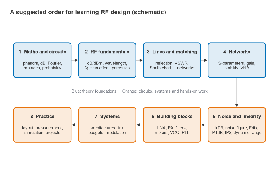
Learning RF design follows a structured path: master the supporting maths and circuit theory, then transmission lines and matching, then network analysis, noise and linearity, and only then the circuit blocks and system architectures that combine them, with hands-on measurement throughout. Most students who stall do so because they jump to amplifier or antenna design before they are fluent with decibels, the Smith chart and S-parameters.
This roadmap turns the RF design guide on this site into an ordered curriculum, from student to working engineer. Each stage lists the pages to read, what you should be able to do before moving on, and a lab exercise that needs only modest equipment. It is part of the RF careers and learning section.
What Maths Do You Need for RF?
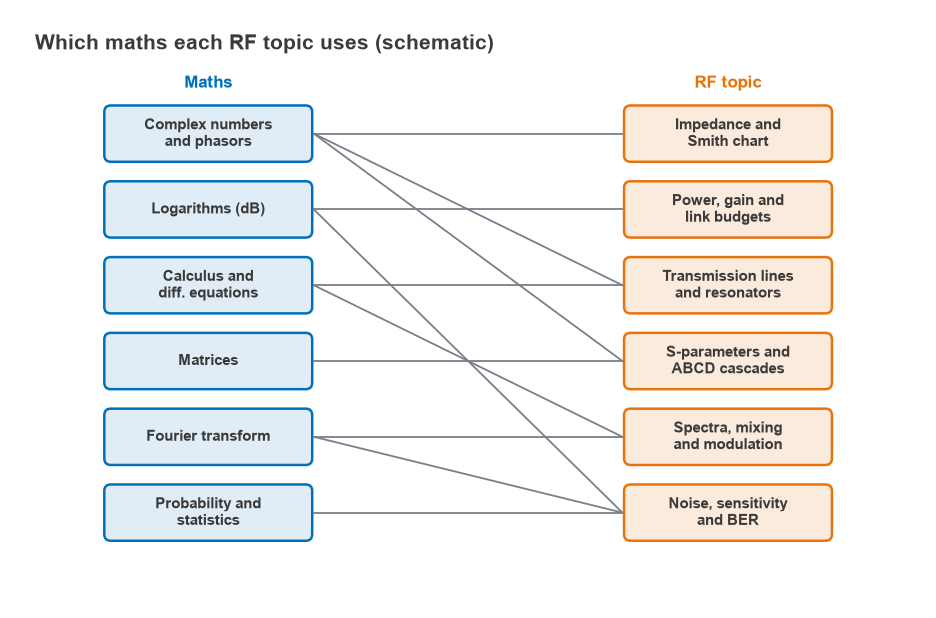
RF design uses a small set of mathematical tools very heavily. Complex numbers and phasors are the most important: every impedance, reflection coefficient and S-parameter is a complex number, and the Smith chart is a map of complex values. Logarithms come next, because gains, losses, power levels and noise are all handled in decibels. Calculus and differential equations underpin transmission line and resonator behaviour, matrices handle S-parameter and ABCD cascades, the Fourier transform explains spectra, mixing and modulation, and probability is needed for noise and bit error rate.
Vector calculus and Maxwell’s equations matter for antennas, waveguides and electromagnetic simulation, but a circuit-level RF designer can start productively with a qualitative understanding and deepen it later. Basic circuit analysis, including Thevenin equivalents, resonance and transistor small-signal models, is assumed throughout.
The Roadmap Stage by Stage
Stage 1 and 2: RF fundamentals
Start with the RF fundamentals hub. Read dB, dBm and dBc until converting between watts, dBm and voltage is automatic, then frequency and wavelength, Q factor, skin effect and component parasitics. The goal is to look at a schematic and see that a 100 pF capacitor at 2.4 GHz has a reactance of about 0.66 Ω and may be close to self-resonance.
Stage 3: transmission lines and matching
Work through the transmission line hub: reflection coefficient, VSWR and return loss, the Smith chart, L-network matching and the microstrip calculator. You are ready to move on when you can plot a load on the Smith chart, design a two-element match by hand and check it with the impedance matching calculator.
Stage 4: network analysis
Learn S-parameters, the different power gain definitions and amplifier stability, and pair them with VNA basics. Reading a Touchstone file and predicting the gain of a cascade from it is the target skill.
Stage 5: noise and linearity
These two topics set the limits of every receiver and transmitter. Read thermal noise and kTB, noise figure, cascaded noise figure, then P1dB, intermodulation and intercept points and dynamic range. After this stage a datasheet should read as a list of trade-offs rather than a list of numbers.
Stage 6: building blocks
Now the circuit blocks make sense: amplifiers including LNA design and biasing, LC filter design, mixers, VCOs and PLL loop filters, and passives such as Wilkinson dividers. Pick one block and design it completely, from specification to simulated S-parameters.
Stage 7: systems
The 20-part radio architectures series ties the blocks into transmitters and receivers. Read it in order, paying particular attention to receiver sensitivity, link budgets, modulation, EVM and PAPR and antennas and propagation. Then write a complete link budget for a radio you own.
Stage 8: practice
Professional work is mostly layout, simulation and measurement. Study RF PCB layout and coplanar waveguide, the measurement pages (spectrum analyzer basics, noise figure measurement, measuring radio performance), and the tools in free RF design software and Python for RF engineers. Build at least one board, measure it and explain every difference from the simulation.
Worked Example: A First System Calculation
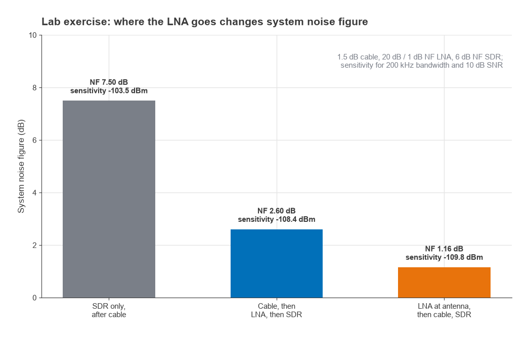
A good test of stages 1 to 5 is to predict the sensitivity of a simple receiving setup before measuring it. Take a software-defined radio with a 6 dB noise figure, connected through coax with 1.5 dB of loss, receiving a signal in a 200 kHz bandwidth that needs 10 dB SNR. A low noise amplifier with 20 dB gain and 1 dB noise figure is available.
- Noise floor: −174 dBm/Hz + 10log10(200,000) = −174 + 53.0 = −121.0 dBm.
- No LNA: a passive loss of 1.5 dB adds directly to the noise figure, so the system noise figure is 1.5 + 6 = 7.5 dB and the sensitivity is −121.0 + 7.5 + 10 = −103.5 dBm.
- LNA after the cable: using the Friis formula with linear values, F = 1.413 + (1.259 − 1)/0.708 + (3.981 − 1)/(0.708 × 100) = 1.413 + 0.366 + 0.042 = 1.821, or 2.60 dB. Sensitivity improves to −108.4 dBm.
- LNA at the antenna, before the cable: F = 1.259 + (1.413 − 1)/100 + (3.981 − 1)/(100 × 0.708) = 1.259 + 0.004 + 0.042 = 1.305, or 1.16 dB. Sensitivity is −109.8 dBm.
The lesson, that loss before the first gain stage costs noise figure decibel for decibel, is one of the most useful in receiver design, and it is easy to verify on the bench with a signal generator and a step attenuator. The underlying theory is in cascaded noise figure, and choosing a suitable amplifier is covered in LNA setups for SDR.
Recommended Labs and Kits
A useful RF bench does not have to be expensive. The items below cover most of the exercises in this roadmap. Buy for the frequency range you intend to work in; a few gigahertz covers most hobby and student work.
- Interconnect kit: good SMA cables, adapters, a 50 Ω load, a short and fixed attenuators (3, 6, 10 and 20 dB). Cheap cables cause more confusing results than cheap instruments.
- A low-cost vector network analyzer: small USB or handheld VNAs are adequate for learning calibration, S-parameters and matching, provided you learn their limits.
- A software-defined radio receiver: for spectrum observation, sensitivity experiments and the noise figure lab above.
- A signal source: a synthesizer evaluation board or a basic signal generator with adjustable level.
- Prototyping material: FR-4 board, copper tape, edge-launch connectors and an assortment of 0402 or 0603 inductors and capacitors.
- Amplifier and filter evaluation boards: they come with documented performance to measure against, which builds trust in your setup.
| Lab | Stage | What you measure |
|---|---|---|
| Cable loss and return loss | 2 to 4 | S21 and S11 of cables and attenuators; compare with datasheet loss per metre |
| LC low-pass filter | 3, 6 | Design a 3-pole filter, build it, compare cutoff and rejection with simulation |
| Microstrip line | 3, 8 | Build a 50 Ω line on FR-4 and measure its impedance and delay |
| Antenna matching | 3 | Measure a small antenna and design an L-network to match it |
| Receiver sensitivity | 5 | Repeat the worked example with an attenuator and SDR |
| Intermodulation | 5 | Combine two tones into an amplifier and measure IM3 versus input level |
Free simulators are good enough for all of these labs. Simulate first, write down the prediction, then measure; the habit of predicting before measuring is what turns a student into an engineer.
From Student to Working Engineer
Employers look for evidence of the full loop: specification, design, layout, measurement and explanation. One well-documented project, such as a matched LNA board with measured gain, noise figure and return loss compared with simulation, says more than a list of courses. Supplement the site with textbooks (see best RF design books), practise with RF interview questions, and keep the wireless terms glossary nearby for unfamiliar terms. Shorter introductions are also available in the step-by-step RF design tutorials and the RF engineering tutorials guide.
Frequently Asked Questions
How do I learn RF design?
Follow a fixed order: fundamentals and decibels, transmission lines and the Smith chart, S-parameters, noise and linearity, then circuit blocks and systems. Pair every topic with a simulation and, where possible, a bench measurement with a low-cost VNA or SDR.
What math do I need for RF?
Complex numbers and phasors, logarithms, calculus with basic differential equations, matrices, the Fourier transform and introductory probability. Vector calculus becomes important for antennas, waveguides and EM simulation.
How long does it take to learn RF design?
It depends heavily on background and time available. Engineers with a solid circuits background can usually work through the fundamentals in a few months of steady study, but independent design competence comes from completing real projects, which takes longer.
Can I learn RF design without expensive equipment?
Yes. Free simulators, a low-cost VNA, an SDR receiver and a set of good cables and attenuators cover most learning exercises. Laboratory-grade instruments become necessary for precise noise figure, phase noise and high-power measurements.
Related Topics
The RF design pillar page links every section in this roadmap. For career context, see careers in RF engineering; for tools, the RF calculators and RF simulation software pages; and for reading, best RF design books.