

Lumped LC filter design is the method of building a filter from discrete inductors and capacitors by scaling a normalized low-pass prototype, a ladder of tabulated g-values, to the required cutoff frequency and system impedance. To design an LC low-pass filter, choose the response type and order from the stopband requirement, look up or calculate the g-values, then convert each one to a capacitance or inductance with two simple scaling formulas.
The method works from a few hundred kilohertz up to roughly 1 to 2 GHz, where component parasitics start to dominate and distributed structures such as the ones in microstrip filter design take over. This page sits under the RF filters hub and assumes the specification terms (cutoff, ripple, stopband attenuation) covered in RF filter specifications.
Butterworth, Chebyshev and Elliptic Responses
The three classical responses trade passband flatness against how fast the attenuation rises above cutoff.
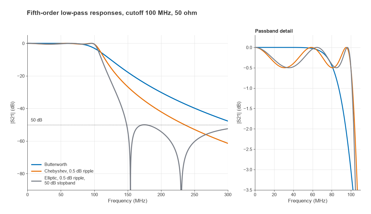
- Butterworth is maximally flat. The insertion loss is |S21|−2 = 1 + (f/fc)2n, so the response has no ripple and is exactly 3.01 dB down at fc. Attenuation far above cutoff rises at 20n dB per decade.
- Chebyshev allows a fixed passband ripple Lr in exchange for a steeper skirt. Here fc is the ripple bandwidth: the response is Lr dB down at cutoff, not 3 dB. Group delay varies more across the passband than for a Butterworth filter of the same order.
- Elliptic (Cauer) filters add transmission zeros in the stopband, made from series or shunt resonators inside the ladder. They give the sharpest transition for a given order, but the stopband attenuation bounces back up between zeros instead of rising monotonically.
For a fifth-order design with a 100 MHz cutoff, the Butterworth filter gives 30.1 dB of attenuation at 200 MHz and the 0.5 dB Chebyshev gives 42.0 dB. An elliptic design with 0.5 dB ripple and a 50 dB minimum stopband reaches 50 dB at about 149 MHz. The Chebyshev needs about 235 MHz to reach the same level and the Butterworth about 316 MHz.
Choosing the order
The minimum order for an attenuation of A dB at a stopband frequency fs follows directly from the response equations:
- Butterworth: n ≥ log10(10A/10 − 1) / [2 log10(fs/fc)]
- Chebyshev: n ≥ cosh−1√[(10A/10 − 1)/(10Lr/10 − 1)] / cosh−1(fs/fc)
Asking for 40 dB at twice the cutoff frequency gives n ≥ 6.64 for Butterworth, so a seventh-order filter, and n ≥ 4.82 for a 0.5 dB Chebyshev, so a fifth-order filter. Two fewer reactive parts is a real saving in loss, board area and tuning effort.
Prototype g-Values
A low-pass prototype is a ladder normalized to a 1 Ω source and a cutoff of 1 rad/s. Each element value gk is either a shunt capacitance in farads or a series inductance in henries. The ladder can start with a shunt capacitor (the pi form) or with a series inductor (the T form); both give the same response.
Butterworth values have a closed form:
gk = 2 sin[(2k − 1)π / 2n], k = 1 … n, with g0 = gn+1 = 1
Chebyshev values are computed recursively. With β = ln[coth(Lr/17.37)], γ = sinh(β/2n), ak = sin[(2k − 1)π/2n] and bk = γ2 + sin2(kπ/n):
g1 = 2a1/γ, gk = 4ak−1ak / (bk−1gk−1)
For odd n the load is 1 Ω, matching the source. Even-order Chebyshev prototypes need a load other than 1 Ω, which is one reason odd orders are used far more often in 50 Ω systems. Elliptic g-values have no simple closed form and are normally taken from published tables or filter synthesis software.
| Element | Butterworth, n = 5 | Chebyshev 0.5 dB, n = 5 |
|---|---|---|
| g1 | 0.618 | 1.706 |
| g2 | 1.618 | 1.230 |
| g3 | 2.000 | 2.541 |
| g4 | 1.618 | 1.230 |
| g5 | 0.618 | 1.706 |
| g6 (load) | 1.000 | 1.000 |
Impedance and Frequency Scaling
Two substitutions turn the prototype into real components for a system impedance R0 and cutoff frequency fc, with ωc = 2πfc:
- Shunt capacitor: Ck = gk / (ωcR0)
- Series inductor: Lk = gkR0 / ωc
The same prototype also gives high-pass and band-pass filters through frequency transformations. For a high-pass filter, each series inductor becomes a series capacitor of 1/(ωcgkR0) and each shunt capacitor becomes a shunt inductor of R0/(ωcgk). For a band-pass filter centred on ω0 with fractional bandwidth FBW, each series inductor becomes a series LC resonator with L = gkR0/(ω0FBW) and C = FBW/(ω0gkR0), and each shunt capacitor becomes a parallel resonator with C = gk/(ω0FBW R0) and L = FBW R0/(ω0gk).
Worked Example: Fifth-Order 100 MHz Low-Pass Filter
The steps below design a fifth-order Butterworth low-pass filter for a 50 Ω system with a 3 dB cutoff of 100 MHz, in the shunt-capacitor-first form.
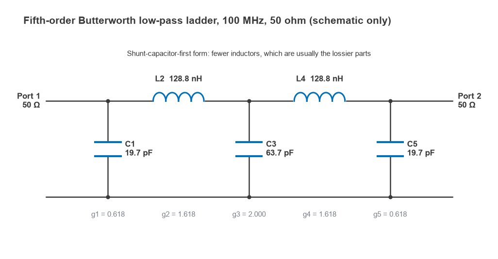
- Compute ωcR0 = 2π × 108 × 50 = 3.1416 × 10¹⁰, and R0/ωc = 50 / 6.2832 × 108 = 7.958 × 10⁻⁸.
- C1 = C5 = 0.618 / 3.1416 × 1010 = 19.67 pF.
- L2 = L4 = 1.618 × 7.958 × 10−8 = 128.8 nH.
- C3 = 2.000 / 3.1416 × 1010 = 63.66 pF.
- Round to available values: 20 pF, 130 nH and 62 pF from the E24 series.
- Simulate the rounded design with realistic component Q, then build and measure it.
The pi form uses three capacitors and two inductors. Since inductors are usually the lossier and more variable parts, starting with a shunt capacitor is the common choice. Rounding to E24 values moves the 3 dB point to about 101.0 MHz and changes the loss at 100 MHz from 3.01 dB to 2.79 dB. At 200 MHz the rounded filter still gives 30.2 dB of rejection, so the change is small.
The same steps applied to the 0.5 dB Chebyshev g-values give C1 = C5 = 54.30 pF, L2 = L4 = 97.85 nH and C3 = 80.88 pF. The Chebyshev version uses larger capacitors and smaller inductors, and its response is 0.5 dB down at 100 MHz rather than 3 dB.
Component Q and Parasitic Effects
Real inductors and capacitors have loss, described by their unloaded quality factor Qu = X/Rs. A series inductor with QL has a series resistance ωL/QL, and a shunt capacitor with QC has a parallel conductance ωC/QC. Small chip inductors around 100 MHz often have Q values somewhere between 30 and 80, while good RF capacitors are typically in the hundreds, so inductor loss usually dominates. Check the Q factor curves in each part’s datasheet at the frequency of interest.
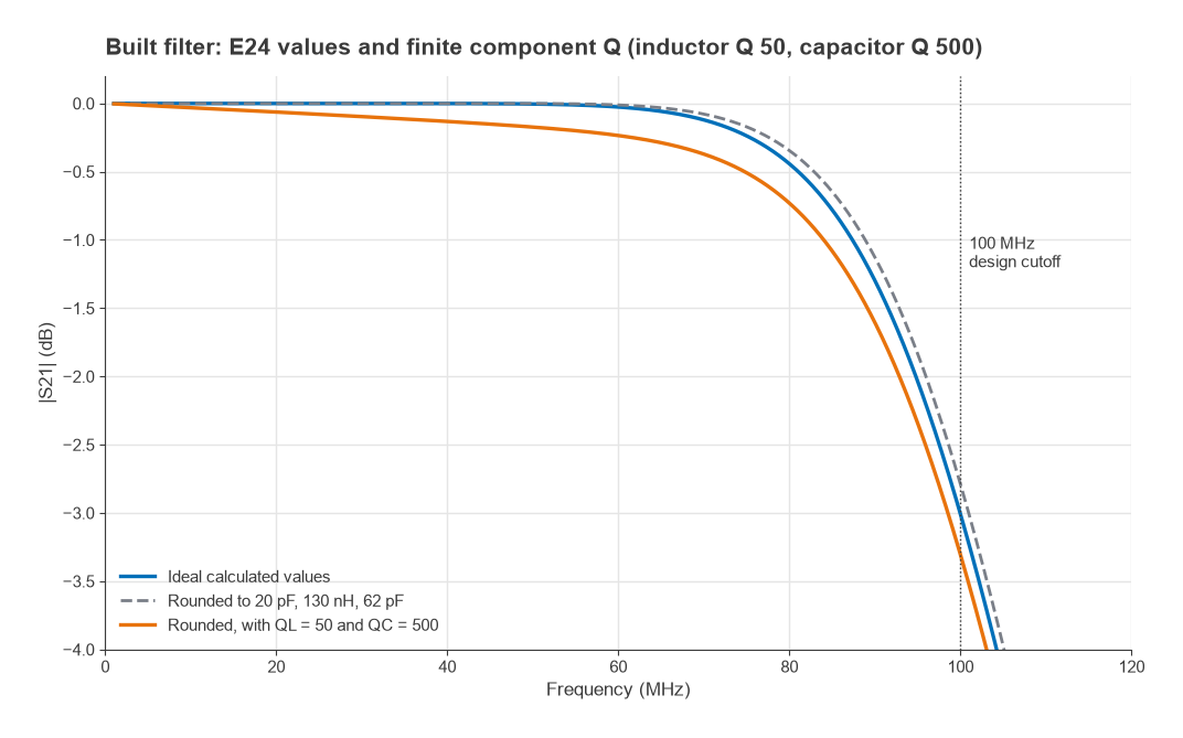
With an inductor Q of 50 and a capacitor Q of 500 (held constant with frequency for simplicity), the rounded 100 MHz filter shows 0.03 dB of loss at 10 MHz, 0.17 dB at 50 MHz and 0.73 dB at 80 MHz, against 0.35 dB at 80 MHz for the lossless version. The loss grows toward cutoff because the stored energy, and so the current in the lossy elements, rises there. Loss in the stopband changes very little: 30.3 dB at 200 MHz instead of 30.2 dB.
Band-pass filters are far more sensitive to Q
For a band-pass filter, Cohn’s approximation gives the midband loss as
IL ≈ 4.343 Σgk / (FBW · Qu) dB
A third-order 0.5 dB Chebyshev band-pass filter (g = 1.596, 1.097, 1.596) with 5% fractional bandwidth and resonators of Qu = 100 has an estimated loss of 4.343 × 4.289 / (0.05 × 100) = 3.73 dB. Halving the bandwidth doubles the loss. This is why narrow band-pass filters move to cavities, ceramic resonators, or SAW and BAW filters, whose resonator Q is far higher than a chip inductor’s.
Self-resonance and layout parasitics
Every inductor has a self-resonant frequency (SRF) set by its winding capacitance, and every capacitor has one set by its lead and pad inductance. Above the SRF the part behaves as the opposite element, which can open up a spurious passband well above cutoff. A practical rule is to pick inductors with an SRF several times the highest stopband frequency that matters. Pad capacitance, via inductance in the shunt capacitor returns and coupling between adjacent inductors all shift the response; the effects are covered in RF component parasitics and RF PCB layout. Mounting inductors at right angles to each other reduces mutual coupling.
From Calculation to Hardware
Hand calculation gets the topology and starting values. Before ordering boards, simulate the ladder with vendor component models or measured S-parameters for each part, then include the pad and via parasitics. On the bench, a vector network analyzer shows S21 and S11 directly. A cutoff that comes out low usually points to extra shunt capacitance from pads; poor stopband depth often points to a shared ground via or coupling between inductors. The impedance matching view of the filter is also useful: |S11| in the passband shows how far the built filter departs from the design.
Frequently asked questions
How do you design an LC low-pass filter?
Choose a response type and calculate the order needed to meet the stopband attenuation. Take the prototype g-values for that order, then scale them with C = g/(2πfcR0) and L = gR0/(2πfc). Round to standard values, simulate with realistic component Q and parasitics, and confirm on a network analyzer.
Butterworth vs Chebyshev: which should I use?
Use Butterworth when flat amplitude and well-behaved group delay matter more than selectivity, for example ahead of a data converter carrying wideband modulation. Use Chebyshev when the stopband requirement is tight and a small passband ripple is acceptable; it often saves one or two elements for the same rejection.
When is an elliptic filter worth the extra parts?
When an interferer or harmonic sits close to the passband edge and must be rejected by a fixed amount. The transmission zeros can be placed on or near the unwanted frequency. The cost is resonators inside the ladder, which are more sensitive to component tolerance, and a stopband that rises and falls rather than increasing steadily.
Up to what frequency do lumped LC filters work?
Chip-component LC filters are common up to roughly 1 to 3 GHz, depending on part size and the order required. Above that, element values become small enough that pad and via parasitics are comparable to the intended values, and distributed microstrip or stripline filters are usually easier to control.
Related topics
The RF filters hub lists every filter technology on the site. For the specifications a filter must meet, see RF filter specifications; for higher-frequency designs, microstrip filter design; and for the transmit-side reconstruction filters these designs often become, DACs and the transmit chain. The wider context is in the RF design pillar, and a hobbyist build log is described in real-world RF filter design and construction.