

RF passive components are the unpowered building blocks that route, split, combine, sample, attenuate and protect signals between the active stages of a radio. The main families are directional couplers, power dividers and hybrids, attenuators, circulators and isolators, switches, detectors, and the connectors and cables that join everything together. Unlike their low-frequency counterparts, most are defined by their behaviour in a matched impedance system, usually 50 Ω.
Passive parts set many of the numbers in a link budget: every dB of insertion loss in front of a receiver adds a dB of noise figure, and every dB after a power amplifier is transmit power wasted as heat. This hub introduces each family, the parameters used to specify it, and the pages that treat it in detail. It is part of the wider RF design reference.
What Passive Components Are Used in RF?
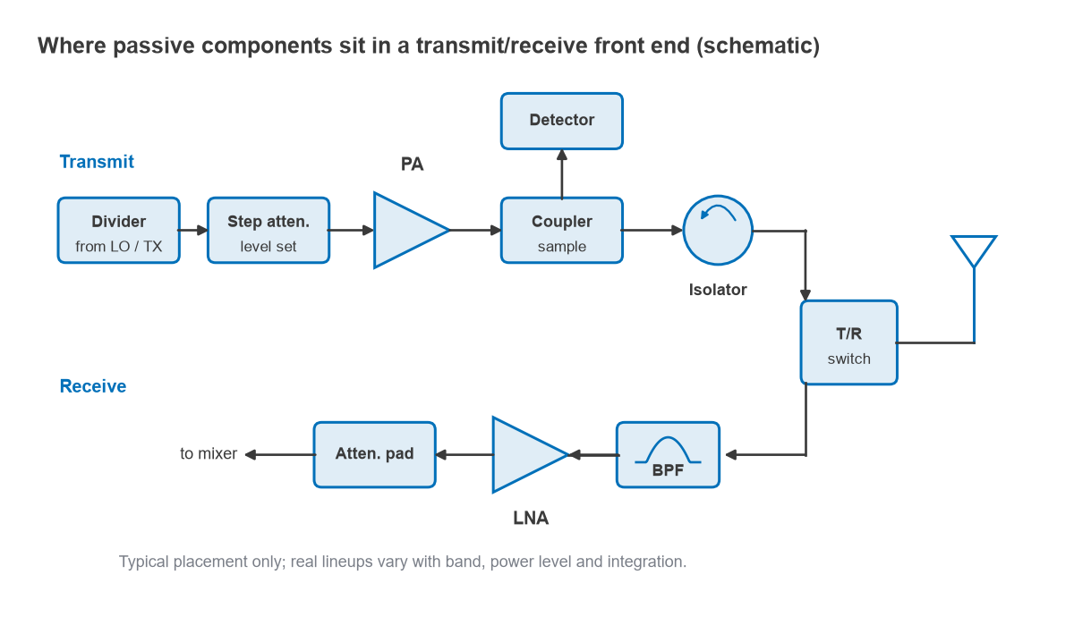
A typical transmit and receive front end uses most of them. A divider splits the LO or transmit signal, a step attenuator sets the drive level, a coupler and detector sample the output power for control, an isolator protects the power amplifier from reflections, and a switch or duplexer connects the antenna to the transmit or receive path. Filters, covered in the RF filters hub, and matching networks, covered under impedance matching, complete the set.
Four parameters appear on almost every passive datasheet: insertion loss, return loss (or VSWR) at each port, isolation between ports that should not be connected, and power handling. All are defined as S-parameters of a multi-port network, so a three-port divider or four-port coupler is fully described by its S-matrix across frequency.
The Main Component Families
Directional couplers
A directional coupler samples a known fraction of the power travelling in one direction on a line. Its coupling factor is C = −10log10(Pcoupled/Pin), and its directivity is the ratio, in dB, between the wanted coupled signal and the leakage from the wave travelling the other way. Removing the sampled power costs the main line very little: an ideal 20 dB coupler takes 1 percent of the power, a main-line loss of 0.044 dB, while a 10 dB coupler takes 10 percent, or 0.46 dB. Couplers are used for power monitoring, reflectometers and VNA test sets. See directional couplers.
Power dividers, combiners and hybrids
A power divider splits one input into equal or weighted outputs; run in reverse it combines them. An ideal two-way split puts 10log10(2) = 3.01 dB less power on each output, a four-way split 6.02 dB. The Wilkinson divider adds two quarter-wave lines of √2 · Z0 (70.7 Ω in a 50 Ω system) and a 2Z0 (100 Ω) resistor between the outputs, so all ports are matched and the outputs are isolated from each other. Hybrids are four-port couplers with a fixed 90° or 180° phase relationship between outputs, used in balanced amplifiers, image-reject mixers and IQ networks. See Wilkinson power dividers and 90 and 180 degree hybrids.
Attenuators
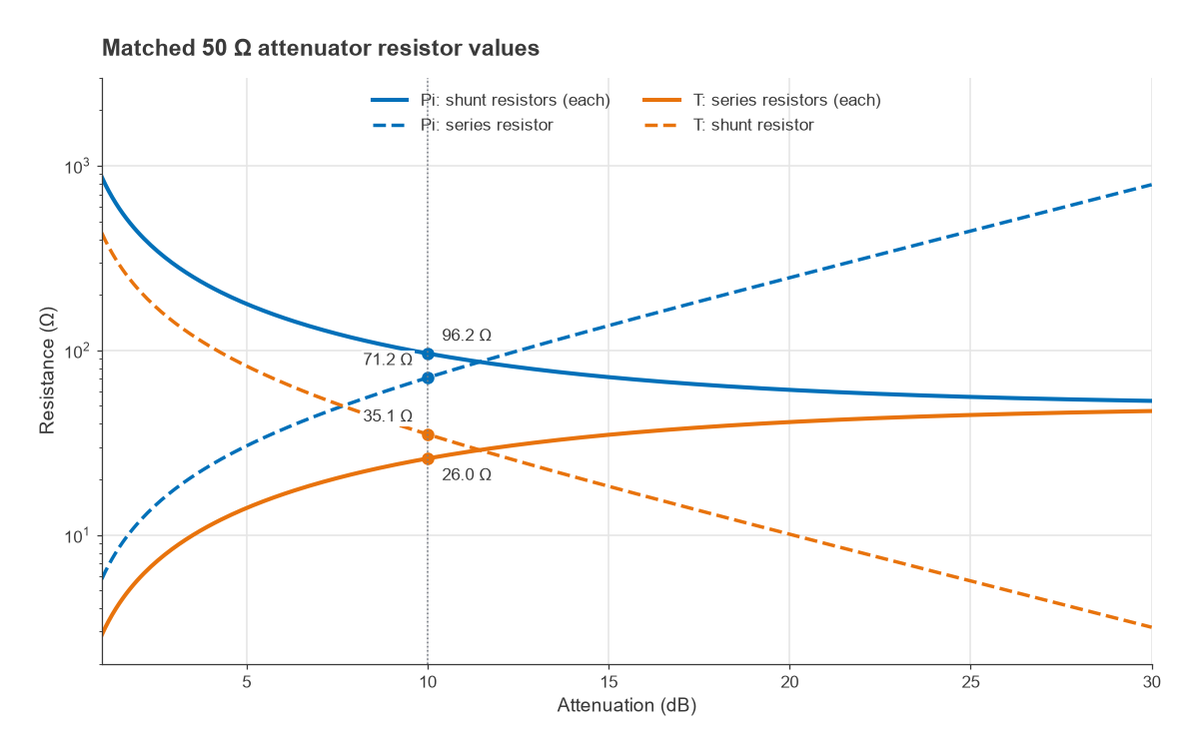
A matched attenuator reduces signal level by a fixed number of dB while presenting Z0 at both ports. With K = 10A/20 for an attenuation of A dB, a Pi attenuator uses two shunt resistors of Z0(K + 1)/(K − 1) and one series resistor of Z0(K2 − 1)/(2K). The T form uses two series resistors of Z0(K − 1)/(K + 1) and one shunt resistor of 2Z0K/(K2 − 1). For 10 dB in 50 Ω, K = 3.162 and the Pi values are 96.2 Ω shunt and 71.2 Ω series; the T values are 26.0 Ω series and 35.1 Ω shunt. A pad also improves match, since a reflection passes through it twice: a 10 dB pad improves the return loss seen at its input by up to 20 dB. Fixed, step and voltage-variable designs are covered in RF attenuators.
Circulators and isolators
A circulator is a three-port, non-reciprocal device, usually built from a magnetized ferrite, that passes power from port 1 to 2, 2 to 3 and 3 to 1, but not in reverse. Terminating one port turns it into an isolator, which passes power forward and absorbs reflections. Isolators protect power amplifiers from load mismatch, and circulators let one antenna serve a transmitter and receiver at the same frequency in radar and some full-duplex systems. See circulators and isolators.
RF switches
Switches route signals between paths: transmit and receive, multiple bands, or a bank of filters. PIN diodes, FETs (including silicon-on-insulator processes) and MEMS contacts are the main technologies, trading insertion loss, isolation, switching speed, power handling and linearity. See RF switches.
Detectors and log amplifiers
A detector converts RF power into a DC voltage for monitoring and control. Schottky diode detectors respond to the square of the input voltage at low levels, so their output is proportional to power, and become peak detectors at higher levels. Logarithmic amplifiers and RMS detectors extend the usable range and give an output in volts per dB. See RF power detectors and log amps.
Connectors and cables
Connectors and cables are a frequent cause of measurement error. Each connector family has an upper frequency set by the size of its coaxial geometry, and each cable has a loss per metre that rises roughly with the square root of frequency at the low end, where conductor loss dominates. See RF connectors and coax cables and transmission line losses.
Common Design Considerations
Most passive components are built either from lumped elements or from transmission-line sections, and the choice depends on frequency and size. Below a few hundred MHz, quarter-wave lines are too long for most boards, so lumped LC equivalents are used. In the low GHz range both forms are common, and above roughly 10 GHz distributed structures in microstrip, stripline or waveguide take over because lumped parts become dominated by their parasitics. Quarter-wave designs are inherently narrowband; multi-section versions trade size for bandwidth.
Topics in This Section
- Directional Couplers: Coupling, Directivity and Design: coupled-line and branch-line couplers and how directivity limits measurement accuracy.
- Power Dividers and Combiners (Wilkinson): the Wilkinson design equations, unequal splits and multi-section bandwidth.
- 90 and 180 Degree Hybrids: branch-line, Lange and rat-race hybrids and their applications.
- RF Attenuators: Pi, T and Step Attenuators (with Calculator): resistor values, power rating and digital step attenuators.
- Circulators and Isolators: ferrite non-reciprocity, isolation and bandwidth.
- RF Switches: PIN Diode, FET and MEMS: technologies compared on loss, isolation, speed and linearity.
- RF Power Detectors and Log Amps: diode, RMS and logarithmic detection.
- RF Connectors and Coax Cables: SMA, N, BNC, 2.92 mm: families, frequency limits and care of precision connectors.
Closely related pages elsewhere include RF baluns, which convert between balanced and unbalanced lines, and duplexers and diplexers, which separate signals by frequency rather than by direction.
Frequently asked questions
What passive components are used in RF?
The main ones are directional couplers, power dividers and combiners, 90° and 180° hybrids, attenuators, circulators and isolators, switches, detectors, filters, baluns, matching networks, connectors and cables. Together they route, sample, split, protect and condition signals between amplifiers, mixers and the antenna.
What is the difference between a coupler and a divider?
A divider splits power into outputs that are usually equal and are both used as signal paths. A directional coupler takes a small, direction-dependent sample, such as 1 percent at 20 dB coupling, while most of the power continues on the main line. A 3 dB hybrid coupler sits between the two, splitting power equally with a defined phase shift.
Why does insertion loss of passive parts matter so much?
Before the first amplifier in a receiver, loss adds directly to noise figure, dB for dB. After a power amplifier, loss reduces output power and turns into heat. The effect is explained in noise figure.
Related topics
Passive components are described with S-parameters and measured with a vector network analyzer, whose test set is itself built from couplers, switches and detectors. Their match is read in terms of VSWR and return loss, and their construction draws on transmission line theory and RF fundamentals. Terms are defined in the wireless terms glossary.