

VSWR (voltage standing wave ratio) is the ratio of the maximum to the minimum voltage along a transmission line, and it measures how well a load is matched to the line’s characteristic impedance. Return loss expresses the same reflection in decibels, as the ratio of incident to reflected power, while mismatch loss is the drop in delivered power that the reflection causes. All three follow from the magnitude of the reflection coefficient, |Γ|, so any one of them can be converted to the others.
These quantities appear on almost every RF datasheet, antenna specification and VNA screen, and they are a standard part of RF design work. This page gives the formulas, a conversion table from VSWR 1.1 to 3.0, the sign convention that causes most of the confusion, a calculator, and the mismatch uncertainty that arises when two imperfect ports are connected together. It builds on the introduction to transmission line theory and on reflection and transmission coefficients.
The Reflection Coefficient Comes First
When a line of characteristic impedance Z0 is terminated in a load ZL, part of the incident wave is reflected. The voltage reflection coefficient at the load is
Γ = (ZL − Z0) / (ZL + Z0)
Γ is complex. Its magnitude runs from 0 (a perfect match) to 1 (an open, a short or a pure reactance), and its angle tells where the load sits on the Smith chart. VSWR, return loss and mismatch loss all discard the angle and keep only |Γ|. That is why a VSWR figure on its own cannot tell you whether a load is too high or too low in impedance, or whether it is inductive or capacitive. For that you need the full complex S11 from a vector network analyzer.
VSWR, Return Loss and Mismatch Loss Formulas
On a lossless line the incident and reflected waves add in phase at some points and cancel at others, a quarter wavelength apart. The voltage maximum is |V+|(1 + |Γ|) and the minimum is |V+|(1 − |Γ|), so
VSWR = (1 + |Γ|) / (1 − |Γ|) and conversely |Γ| = (VSWR − 1) / (VSWR + 1)
VSWR is a pure ratio, often written as 1.5:1, and it runs from 1 for a perfect match to infinity for total reflection.
Return loss is the ratio of incident power to reflected power, in decibels:
RL = −20 log10|Γ| dB
The factor is 20 rather than 10 because Γ is a voltage ratio and power goes as its square. Mismatch loss is the ratio of incident power to the power actually absorbed by the load:
ML = −10 log10(1 − |Γ|2) dB
Mismatch loss is not dissipated anywhere in the load. The reflected power travels back towards the source, where it may be absorbed by the source resistance, re-reflected, or dumped in an isolator. If you need a refresher on the decibel arithmetic, see dB, dBm and related units.
Worked example: a 75 Ω load on a 50 Ω line
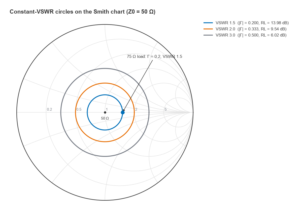
- Γ = (75 − 50) / (75 + 50) = 25 / 125 = 0.200.
- VSWR = 1.2 / 0.8 = 1.50.
- RL = −20 log(0.2) = 13.98 dB.
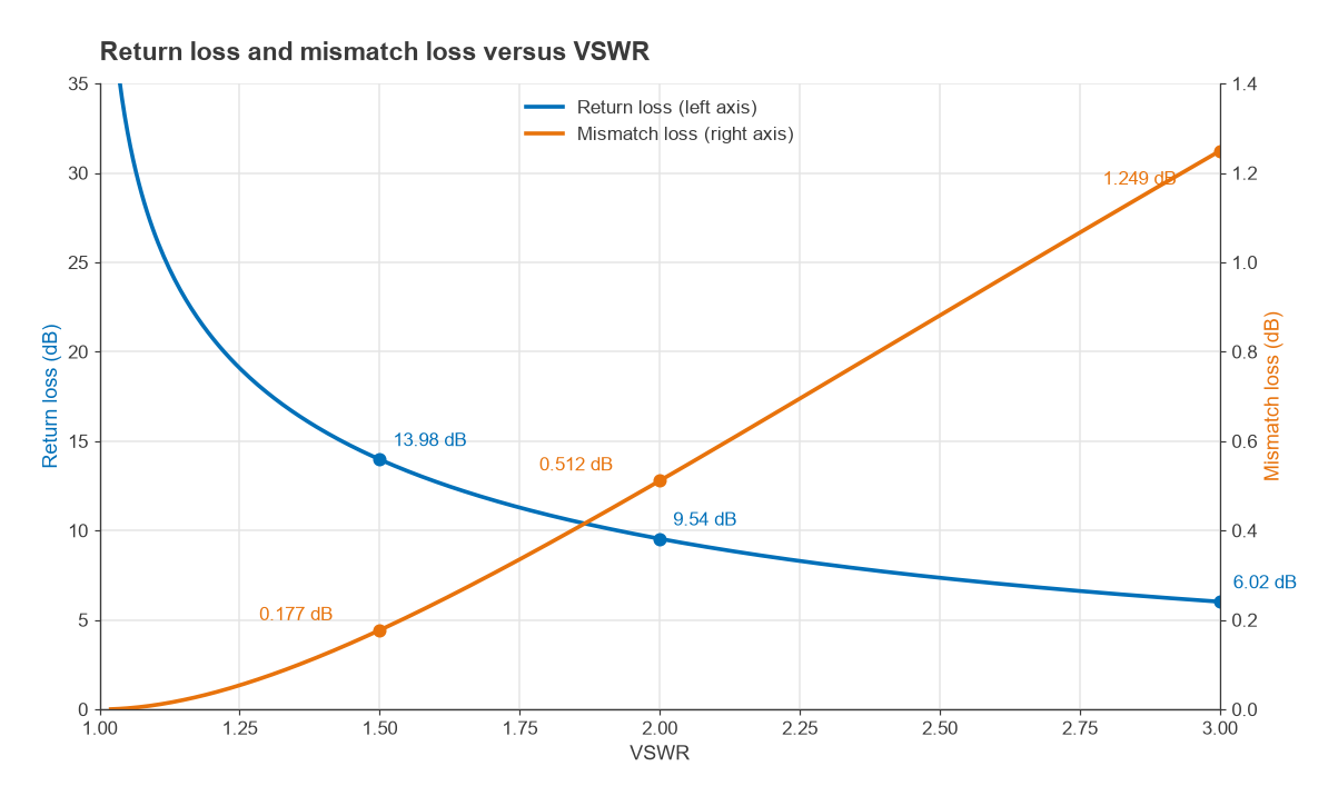
- Reflected power fraction = 0.22 = 4.0 %, so ML = −10 log(0.96) = 0.177 dB.
A 50 % impedance error therefore costs less than 0.2 dB of delivered power. This is the main practical lesson of mismatch loss: modest mismatches waste very little power. The reasons to care about them lie elsewhere, in gain ripple, filter response distortion, amplifier stability and power-amplifier stress. At VSWR 2.0 a 100 W transmitter sends 11.1 W back towards its output stage, which is a protection problem long before it is an efficiency problem.
VSWR to Return Loss Conversion Table
The table below was computed from the formulas above. Return loss and mismatch loss are rounded to two and three decimal places.
| VSWR | |Γ| | Return loss (dB) | Reflected power (%) | Mismatch loss (dB) |
|---|---|---|---|---|
| 1.1 | 0.048 | 26.44 | 0.23 | 0.010 |
| 1.2 | 0.091 | 20.83 | 0.83 | 0.036 |
| 1.3 | 0.130 | 17.69 | 1.70 | 0.075 |
| 1.4 | 0.167 | 15.56 | 2.78 | 0.122 |
| 1.5 | 0.200 | 13.98 | 4.00 | 0.177 |
| 1.6 | 0.231 | 12.74 | 5.33 | 0.238 |
| 1.7 | 0.259 | 11.73 | 6.72 | 0.302 |
| 1.8 | 0.286 | 10.88 | 8.16 | 0.370 |
| 1.9 | 0.310 | 10.16 | 9.63 | 0.440 |
| 2.0 | 0.333 | 9.54 | 11.11 | 0.512 |
| 2.5 | 0.429 | 7.36 | 18.37 | 0.881 |
| 3.0 | 0.500 | 6.02 | 25.00 | 1.249 |
Two shortcuts are worth remembering. A return loss of 10 dB means 10 % of the power is reflected (VSWR about 1.92), and 20 dB means 1 % (VSWR about 1.22). Return loss changes rapidly near a good match and slowly near a bad one, so “improving” a load from 25 dB to 30 dB return loss changes almost nothing in delivered power.
Standing Waves on the Line
The name VSWR comes from the measurement it originally described. With a slotted line, a probe was moved along the line and the detected voltage rose and fell with a period of half a wavelength. For |Γ| = 1/3 the normalised voltage swings between 1.333 and 0.667, a ratio of exactly 2. A matched line shows no ripple at all, and a short or open shows nulls that go to zero, giving infinite VSWR.
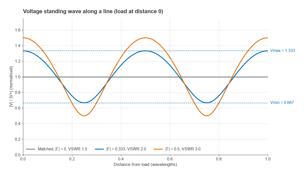
The voltage maxima matter for power handling. At VSWR 3.0 the peak voltage on the line is 1.5 times the matched value, so the peak power-equivalent stress is 1.52 = 2.25 times higher. Cable and connector ratings, discussed in transmission line losses and power handling, are normally given for a matched line and must be derated when the VSWR is high.
Return Loss Sign Convention and S11
Return loss, defined as a loss, is a positive number for any passive load: 14 dB return loss means the reflected wave is 14 dB below the incident one. S11 in dB is 20 log|Γ|, which is negative for the same load, here −14 dB. The two describe the same physics with opposite signs.
In practice many datasheets and instrument screens write “return loss −14 dB” when they mean S11 = −14 dB. The intent is almost always clear from context: a “better” match is a larger positive return loss or a more negative S11. When writing a specification, it is cleaner to say either “return loss ≥ 14 dB” or “S11 ≤ −14 dB”, not a mixture. Converting S11 = −14 dB gives |Γ| = 10−14/20 = 0.1995, VSWR = 1.498 and ML = 0.176 dB.
A related trap is cable loss. A load measured through a cable with one-way loss A dB shows a return loss that is better by 2A dB, because the reflected wave crosses the cable twice. An open circuit at the end of a cable with 3 dB loss reads as 6 dB return loss, which looks like VSWR 3.0 rather than infinity. Antenna VSWR measured at the bottom of a long feeder is flattered in exactly this way.
VSWR Circles on the Smith Chart
Because VSWR depends only on |Γ|, every load with the same VSWR lies on a circle centred on the middle of the Smith chart. The radius of that circle is |Γ|. A specification such as “VSWR ≤ 2.0 across the band” is therefore a statement that the measured trace must stay inside the |Γ| = 0.333 circle. Moving along a lossless line rotates the load point around the centre without changing its radius, which is why line length changes the impedance seen by the source but not the VSWR. Bringing the trace back to the centre is the job of impedance matching.
What Is a Good VSWR?
The answer depends on the application, and the values below are typical engineering targets rather than limits from any one standard.
- Test cables, attenuators, terminations and calibration standards: commonly better than 1.2 (above about 20 dB return loss), and much better for metrology parts.
- Amplifier and filter ports in a 50 Ω system: often specified around 1.5 to 2.0 (roughly 10 to 14 dB return loss).
- Antennas: 2.0 is a common bandwidth definition, and some small or wideband antennas are specified to 3.0.
- Transmitter outputs: many power amplifiers fold back power or trip protection when the load VSWR rises past a few to one.
Mismatch Uncertainty Between Two Ports
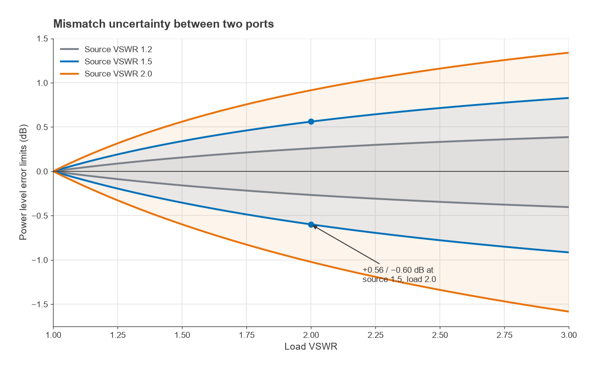
Mismatch loss assumes a matched source. When the source is also mismatched, the wave reflected by the load is partly re-reflected by the source, and the multiple reflections add with a phase that depends on frequency and line length. The power delivered relative to the matched case then falls somewhere between two limits:
Mismatch uncertainty = 20 log10(1 ± |ΓS||ΓL|) dB
This is the dominant error in many power measurements and in cascaded gain predictions, because the phase of the product is usually unknown.
Worked example: signal generator into an amplifier
A source with VSWR 1.5 (|ΓS| = 0.200) drives an amplifier input with VSWR 2.0 (|ΓL| = 0.333). The product is 0.0667, so the limits are 20 log(1.0667) = +0.56 dB and 20 log(0.9333) = −0.60 dB. The level at the amplifier input is uncertain by about 1.2 dB peak to peak, which is far more than the 0.51 dB mismatch loss of the load alone. With a source VSWR of 2.0 and a load VSWR of 3.0 the window widens to +1.34 / −1.58 dB. Adding a well-matched attenuator in front of the device under test is the usual cure, because it improves the effective source match by twice its attenuation.
VSWR, Return Loss and Γ Calculator
Enter any one value and press Convert. The second part computes the mismatch uncertainty limits for a source and load VSWR.
Convert reflection quantities
Mismatch uncertainty
Frequently Asked Questions
What is VSWR?
VSWR is the ratio of maximum to minimum voltage on a transmission line caused by a reflection at the load. It equals (1 + |Γ|)/(1 − |Γ|), where Γ is the reflection coefficient. A value of 1.0 means a perfect match and larger values mean more reflected power.
How do you convert VSWR to return loss?
First find |Γ| = (VSWR − 1)/(VSWR + 1), then RL = −20 log10|Γ|. For VSWR 2.0, |Γ| = 0.333 and the return loss is 9.54 dB. To go the other way, |Γ| = 10−RL/20.
What is mismatch loss?
Mismatch loss is the reduction in power delivered to a load because part of the incident power is reflected, ML = −10 log(1 − |Γ|2). It is small for moderate mismatches: 0.18 dB at VSWR 1.5 and 0.51 dB at VSWR 2.0. It assumes a matched source; with a mismatched source, mismatch uncertainty applies as well.
Is return loss positive or negative?
Strictly, return loss is positive for a passive load, because it is defined as a loss. S11 in dB carries the opposite sign and is negative. Many documents use “return loss” loosely for S11, so check the sign convention before comparing numbers.
What is a good VSWR?
Below 1.5 is good for most 50 Ω components, and 2.0 is a common acceptance limit for antennas. Test accessories and terminations are usually much better than 1.2. The right target depends on how much ripple, uncertainty and reflected power the system can tolerate.
Related Topics
- Transmission line terminations: what opens, shorts and reactive loads do to the line.
- S-parameters: S11, S21 and how reflection fits the two-port picture.
- Types of transmission lines and transmission line parameters.
- Wireless terms glossary for short definitions of related terms.