

Noise in RF systems is the random, unwanted signal energy that every resistor, transistor, oscillator and antenna adds to a wanted signal, and it sets the lower limit of what a receiver can detect. The main sources in RF circuits are thermal noise, shot noise, flicker (1/f) noise and phase noise, plus noise received from the environment through the antenna.
Noise is the reason a receiver has a sensitivity limit, a link has a maximum range and a transmitter needs a spectral mask. Within RF design, the noise branch sits alongside linearity: one sets the weakest signal a system can handle, the other the strongest. This page introduces the noise mechanisms, the figures of merit used to describe them, and the articles in this section that cover each one in depth.
The Main Sources of Noise in RF Circuits
Thermal noise
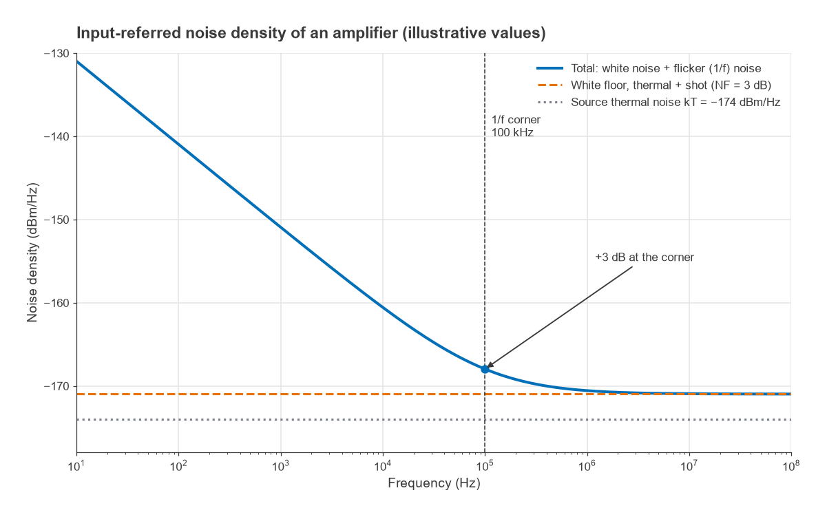
Thermal, or Johnson-Nyquist, noise comes from the random motion of charge carriers in any resistance above absolute zero. Its open-circuit voltage is vn = √(4kTRB), about 0.9 µV rms for 50 Ω in 1 MHz at room temperature, and the power it delivers to a matched load is kTB, independent of the resistance. At 290 K that is −174 dBm per hertz of bandwidth. Thermal noise is white and Gaussian and is present in every lossy part: resistors, cables, filters, the channel resistance of FETs and the base resistance of bipolar transistors.
Shot noise
Shot noise arises because current across a junction is carried by discrete charges arriving at random times. Its mean-square current is in2 = 2qIB, where q is the electron charge and I the DC current. A 1 mA current in 1 MHz carries about 17.9 nA rms of shot noise. It is white over the RF range and is the dominant noise mechanism in diodes, photodetectors and the collector current of bipolar transistors. It is one reason LNA noise figure depends on bias current.
Flicker (1/f) noise
Flicker noise has a power density that rises roughly as 1/f towards low frequencies. It is associated with traps and surface effects in semiconductors and is usually much stronger in MOSFETs than in bipolar devices. Its strength is described by the corner frequency where it equals the white noise floor; above the corner the device looks white, below it the 1/f slope dominates. Flicker noise matters most where signals sit near DC, as in zero-IF receivers, and where it is up-converted around a carrier in oscillators.
Phase noise
Phase noise is random fluctuation in the phase of an oscillator, seen in the spectrum as noise skirts either side of the carrier and quoted in dBc/Hz at a given offset. It is not a separate physical mechanism but the result of thermal, shot and flicker noise inside the oscillator and its PLL. In a receiver, phase noise on the local oscillator mixes strong nearby signals into the wanted channel, an effect called reciprocal mixing; in a transmitter it raises adjacent-channel leakage and degrades EVM. Radio Architectures Part 10 covers how synthesizers shape it.
External noise
An antenna also receives noise from its surroundings: thermal radiation from the ground and atmosphere, cosmic background, and man-made noise from electrical equipment. It is described by an antenna noise temperature. At low VHF frequencies external noise often exceeds receiver noise, so a very low noise figure buys little. At microwave frequencies an antenna pointed at clear sky can be much colder than 290 K, and the receiver’s own noise dominates.
How Noise Is Measured and Specified
RF engineers rarely work with noise voltages. They use a small set of power-based figures of merit, each covered by its own article:
- Noise power and noise density, in dBm and dBm/Hz, referred to kTB.
- Noise figure and noise factor, which describe how much a component degrades SNR relative to a 290 K source.
- Noise temperature, the linear equivalent preferred for very low-noise systems.
- Phase noise in dBc/Hz, and integrated jitter for clocks.
- SNR and Eb/N0, which connect noise to demodulation performance and bit error rate.
All of these come together in one line of arithmetic. A receiver with noise figure NF and noise bandwidth B has an input-referred noise floor of −174 + 10 log B + NF dBm. For a 1 MHz bandwidth and a 5 dB noise figure that is −174 + 60 + 5 = −109 dBm. Add the SNR the demodulator needs and the result is the sensitivity.
Articles in This Section
- Thermal noise, kTB and the −174 dBm/Hz noise floor: where the reference floor comes from, how bandwidth scales it, and noise bandwidth versus 3 dB bandwidth.
- Noise figure and noise factor: definitions, the 290 K reference, lossy components and typical values by device type.
- Cascaded noise figure (Friis formula): a step-by-step method, a worked receiver chain, the mast-mounted LNA case and a calculator.
- Noise temperature and antenna temperature: the linear description used for satellite and low-noise systems.
- Receiver sensitivity (Radio Architectures Part 4): turning noise floor and required SNR into a sensitivity specification.
- Phase noise: definition, units and impact: dBc/Hz, jitter, reciprocal mixing and EVM.
- SNR, Eb/N0 and required SNR by modulation: the link between noise and bit error rate.
Where Noise Enters a Receiver
Following the signal from the antenna shows how the topics connect. The antenna delivers the wanted signal along with external noise. Every lossy part before the first amplifier, such as a cable, switch or preselector, adds its loss directly to the noise figure. The low noise amplifier then sets most of the system noise figure, provided its gain is high enough to swamp the stages behind it. The mixer adds its own noise and passes on the LO’s phase noise. The channel filter sets the noise bandwidth, and the ADC adds quantisation noise and clock-jitter noise that must sit below the analog noise floor.
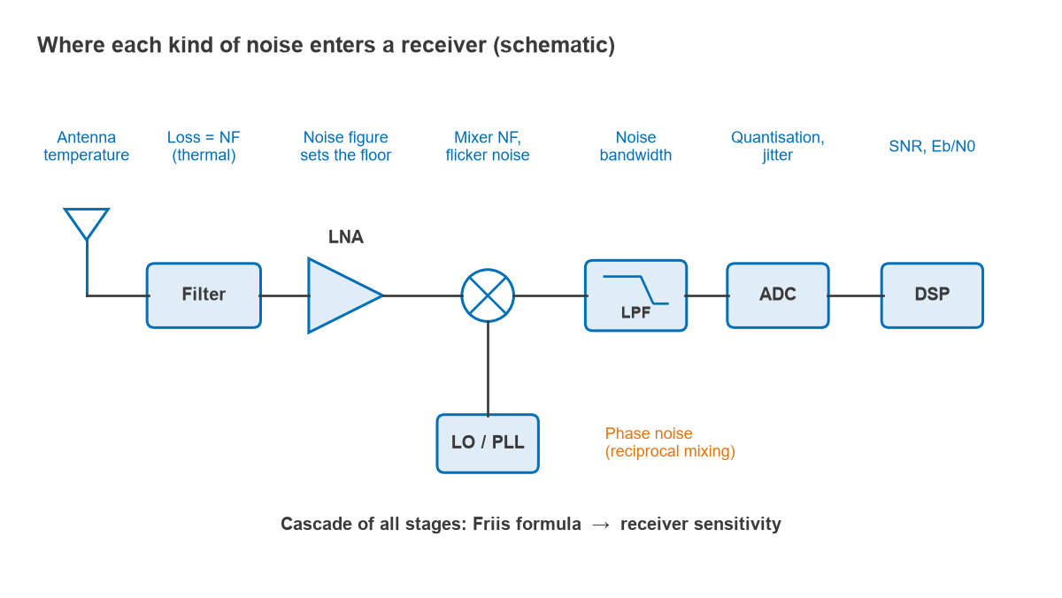
The same stage-by-stage view is the basis of the RF link budget, which adds transmitter power, antenna gains and path loss to find whether the received signal clears the noise floor with enough margin. Measuring noise in practice is covered under noise figure measurement and phase noise measurement.
Frequently Asked Questions
What are the sources of noise in RF circuits?
The main internal sources are thermal noise in resistances, shot noise in junction currents and flicker noise in semiconductors. Oscillators convert these into phase noise. External noise reaches the receiver through the antenna from the sky, the ground and man-made sources.
Which noise source matters most in a receiver?
For most receivers at UHF and above, thermal noise from the source plus the noise added by the first stages, summarised by the cascaded noise figure, sets the floor. Phase noise becomes the limit when strong signals sit close to a weak wanted signal. At low frequencies external noise can dominate everything else.
Can noise be filtered out?
Noise outside the wanted channel can be filtered, which is why narrowing the bandwidth lowers the noise floor. Noise that falls inside the channel cannot be separated from the signal by filtering. It can only be kept small at its source, through low-noise design, cooling or a better antenna.
Related Topics
Noise is one half of the dynamic range picture; the other half is covered under RF linearity. For component choices driven by noise performance, see how to choose an LNA. Short definitions of the terms used here are in the wireless terms glossary.