

An antenna is a transducer that converts guided electromagnetic energy on a transmission line into a wave radiating through space, and converts an incoming wave back into a voltage at its terminals. It works because time-varying currents on a conductor whose size is comparable to the wavelength launch fields that detach and propagate. In RF design, the antenna and the propagation path together set how much signal reaches the receiver.
This section of the RF design reference covers the antenna as a circuit component and the path as a loss term. It does not try to replace a full antenna theory course. Its aim is narrower: to give circuit and system designers the parameters, equations and layout rules they need to specify an antenna, connect it to a radio, and predict a link.
How Antennas Work
Any accelerating charge radiates. On a short wire carrying an RF current, the fields close to the conductor are mostly reactive: energy flows out and back each cycle, like the field of a capacitor or inductor. Further away, beyond roughly λ/2π for a small antenna, a component that falls off as 1/d dominates. That component carries power away permanently and is the radiated wave. An antenna is a structure shaped so that a large share of the input power goes into this radiating component rather than being stored or lost as heat.
The half-wave dipole shows the idea clearly. Two conductors, each about a quarter wavelength long, are fed at the centre. The current is largest at the feed and falls to zero at the open ends, and at resonance the input impedance is close to 73 Ω resistive. At 2.4 GHz a half wavelength in free space is 6.25 cm; practical dipoles are cut a few percent shorter to account for end effects and conductor thickness. Shorter structures still radiate, but their radiation resistance falls quickly and they need matching networks to present a usable impedance, which is the central problem of small antennas in handheld products.
Two properties make antenna analysis manageable. Reciprocity means that an antenna’s pattern, gain and impedance are the same whether it transmits or receives. Linearity means that a passive antenna adds no new frequencies, so it can be described entirely by its impedance, efficiency and directional gain at each frequency.
Radiation pattern, directivity and gain
No real antenna radiates equally in all directions. The radiation pattern describes the relative field strength versus angle, and directivity D is the peak radiation intensity divided by the average over all directions. Gain G = η · D includes the radiation efficiency η, so it accounts for conductor and dielectric loss. A short dipole has a directivity of 1.5 (1.76 dBi), and the half-wave dipole reaches 1.64 (2.15 dBi) with a slightly narrower beam: a half-power beamwidth of about 78° compared with 90°. Higher-gain antennas, such as patches, Yagis, horns and arrays, concentrate energy into a narrower beam; they do not create power.
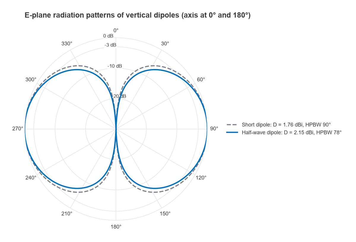
Gain, efficiency, beamwidth, polarization, bandwidth and impedance are defined precisely on the antenna parameters page.
From Antenna to Link: Propagation
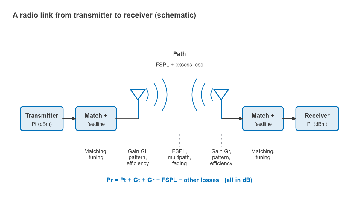
Once the wave leaves the transmitting antenna, the path decides what fraction arrives. In free space the Friis transmission equation gives the received power, in dB units:
Pr = Pt + Gt + Gr − FSPL, with FSPL(dB) = 20log10(dkm) + 20log10(fMHz) + 32.44
For example, two half-wave dipoles (2.15 dBi each) 100 m apart at 2.4 GHz see a free-space path loss of 80.04 dB, so a +20 dBm transmitter delivers about −55.7 dBm to the receiver. Real paths add excess loss from obstructions, reflections, absorption and fading, which is why link budgets carry margin. Matching losses at each end, and the cable between antenna and radio, add further decibels that are easy to overlook.
Antenna and propagation questions also appear throughout the Radio Architectures series. Part 17 of that series, Antennas and Propagation for Radio Designers, treats the topic from the system level, and the Radio Architectures index lists every part.
Topics in This Section
- Antenna Parameters: Gain, Directivity, Efficiency, Beamwidth: the figures on an antenna datasheet and how they relate to each other.
- Free-Space Path Loss (with Calculator): the derivation of FSPL, why it grows with frequency, and a worked link example.
- Radio Propagation Basics: Multipath, Fading, Fresnel Zones: what happens on real paths beyond free space.
- PCB Antenna Design (Inverted-F, Meander, Patch): printed antennas for compact wireless products, with layout and ground-plane rules.
- Patch Antenna Design Equations: dimensions, feed position and bandwidth of the rectangular microstrip patch.
- Antenna Matching and Tuning in Products: how enclosures, hands and ground planes detune an antenna, and how matching networks correct it.
Related material elsewhere on the site
- Advanced antenna design in RF engineering: arrays, wideband and reconfigurable antennas.
- Multiple antennas and MIMO, beamforming and phased array design: what changes when several antennas work together.
- RF link budget: combining antenna gain, path loss and receiver sensitivity into range and margin.
- VSWR and return loss and the Smith chart: the tools for reading and correcting antenna impedance.
- RF baluns: connecting balanced antennas such as dipoles to unbalanced coaxial and microstrip lines.
What an RF Designer Needs from an Antenna
From the radio’s point of view, an antenna is a one-port load with a frequency-dependent impedance and a directional, lossy coupling to the outside world. Four questions usually decide whether it is suitable:
- Is it matched? Return loss across the operating band, measured in the final enclosure, determines how much power is reflected. A 10 dB return loss reflects 10 percent of the power, a mismatch loss of about 0.46 dB.
- Is it efficient? Small antennas near ground planes, batteries and plastics can lose several dB to dissipation, and that loss counts directly against the link.
- Does the pattern suit the application? A ceiling access point, a handheld and a point-to-point link want very different coverage.
- Is the polarization right? A linearly polarized antenna receiving a circularly polarized signal loses about 3 dB; cross-polarized linear antennas can lose 20 dB or more.
The matching question links this section to impedance matching and to transmission line theory. The efficiency and pattern questions are usually answered by measurement in an anechoic chamber or by EM simulation, since the product around the antenna changes both.
Frequently asked questions
How do antennas work?
An RF current on a conductor produces electric and magnetic fields. When the conductor is a significant fraction of a wavelength long, part of that field detaches and travels away as a wave carrying power. On receive the process runs in reverse, and by reciprocity the antenna has the same pattern and impedance in both directions.
Does a higher-gain antenna produce more power?
No. A passive antenna can only redistribute power in angle. Higher gain in one direction is paid for with lower radiation in others, and the total radiated power is the input power multiplied by the radiation efficiency.
Why is a dipole half a wavelength long?
At a length near λ/2 the dipole is resonant: its input reactance passes through zero and its resistance is close to 73 Ω, which is easy to match to 50 Ω or 75 Ω lines. Other lengths radiate too, but they present reactive impedances that need extra matching.
Related topics
Antennas connect to the rest of the radio through transmission lines and are characterized with S-parameters. The physics behind radiated waves is covered in properties of electromagnetic waves and the foundational RF fundamentals hub. Unfamiliar terms are defined in the wireless terms glossary.