

An RF circuit is nonlinear when its output is no longer a scaled copy of its input, so that doubling the input does not double the output and new frequencies appear that were not present at the input. Linearity in RF design is the study of how far a circuit departs from that ideal, which signal levels make the departure visible, and which specifications (P1dB, IP3, IP2, SFDR, blocking) put numbers on it.
Every active device is nonlinear to some degree. Transistor current depends exponentially or quadratically on control voltage, junction and drain capacitances change with voltage, and supply rails and temperature move with the signal. At low levels these effects are small enough to ignore. At the levels found in a crowded band, or at the output of a power amplifier, they set the limit on what a radio can do. This hub introduces the model behind all linearity specifications and links to the pages that treat each one in detail, as part of the wider RF design reference.
The Power-Series Model of a Nonlinear Circuit
For a circuit that is only mildly nonlinear and has no memory, the output y can be written as a Taylor series in the input x:
y(t) = a1x(t) + a2x2(t) + a3x3(t) + …
The coefficient a1 is the small-signal voltage gain. The a2 term comes from asymmetry in the transfer curve, and a3 from its curvature. For a compressive amplifier a3 has the opposite sign to a1, which is why gain falls as the drive rises. Higher-order terms exist, but the first three explain almost every specification on an amplifier or mixer datasheet.
Substituting a single tone x = A cos(ωt) gives a fundamental of amplitude a1A + (3/4)a3A3, a second harmonic of (1/2)a2A2 and a third harmonic of (1/4)a3A3. The first expression already contains gain compression: once (3/4)|a3|A2 is no longer small compared with a1, the fundamental falls below the straight-line extrapolation. Setting that shortfall to 1 dB gives the 1 dB compression point.
Two tones and intermodulation
With two tones of equal amplitude A at f1 and f2, the cubic term produces products at 2f1 − f2 and 2f2 − f1 with amplitude (3/4)|a3|A3. These third-order intermodulation (IM3) products are the troublesome ones, because they sit right next to the wanted signals where no filter can remove them. In dB terms they grow 3 dB for every 1 dB increase in input, while the fundamental grows 1 dB. Extrapolating the two straight lines until they meet defines the third-order intercept point, IP3. The square term produces second-order products at f2 − f1 and f1 + f2, which grow 2 dB per dB and define IP2.
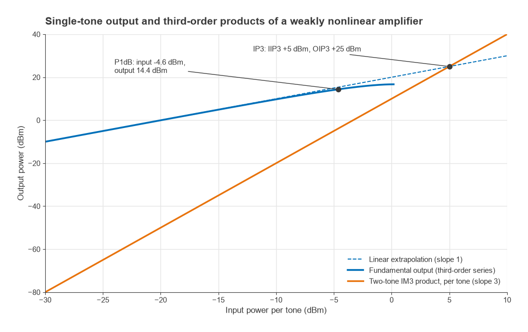
Those slopes give the two working equations used throughout this branch. For input power Pin per tone, output power Pout per tone and gain G, all in dB units:
- PIM3,out = 3Pin − 2·IIP3 + G = 3Pout − 2·OIP3
- PIM2,out = 2Pin − IIP2 + G
For a pure third-order nonlinearity the same coefficients fix both the compression point and the intercept point, and the input-referred IP3 lands about 9.6 dB above the input 1 dB compression point. Real devices are close to that relationship but not bound by it, which is why datasheets list both numbers.
A worked example
Take an amplifier with 20 dB gain, IIP3 = +5 dBm and IIP2 = +25 dBm, driven by two tones of −20 dBm each at 100 MHz and 110 MHz. The fundamentals come out at about 0 dBm. The IM3 products at 90 MHz and 120 MHz are 3(−20) − 2(5) + 20 = −50 dBm, 50 dB below each tone. The second-order products at 10 MHz and 210 MHz are 2(−20) − 25 + 20 = −45 dBm. A time-domain simulation of the same power series, transformed with an FFT, returns exactly those levels, along with second harmonics at −51 dBm and third harmonics at about −59.5 dBm.
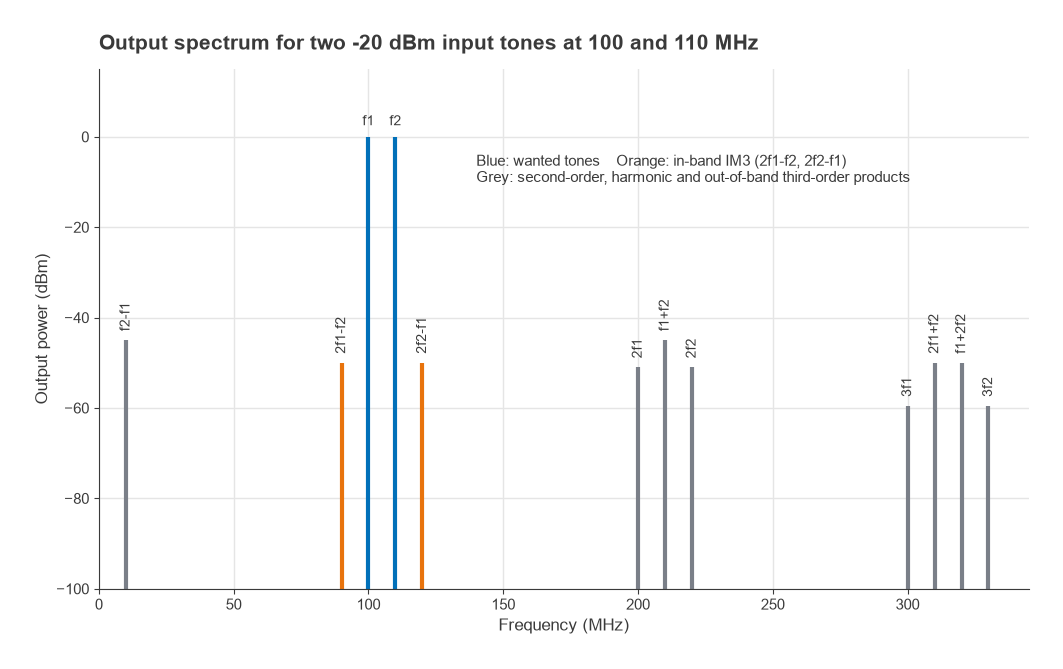
Raise each input tone by 10 dB, to −10 dBm, and on the straight-line model the IM3 products climb 30 dB to −20 dBm, only 30 dB below tones of about +10 dBm. In practice the amplifier is by then within a few dB of compression, so the real figures are somewhat worse. That threefold growth is why a receiver that behaves well at moderate levels can collapse quickly when a strong neighbour appears.
Where Nonlinearity Shows Up in a Radio
The same handful of coefficients appears under different names depending on the signal environment:
| Effect | Main cause | Usual specification | Where it hurts |
|---|---|---|---|
| Gain compression | a3 opposing a1 | P1dB, Psat | PA output, receiver overload |
| Third-order intermodulation | a3 | IIP3, OIP3 | Adjacent signals in receivers, spectral regrowth in transmitters |
| Second-order distortion | a2 | IIP2 | Zero-IF and wideband receivers |
| Harmonics | a2, a3 | dBc at 2f, 3f | Transmitter spurious emissions |
| Blocking and desensitization | a3 with one strong tone | Blocking level, desense in dB | Receivers near strong transmitters |
| AM-AM and AM-PM conversion | Level-dependent gain and phase | Degrees per dB, EVM, ACLR | High-PAPR transmitters |
The lower end of the usable signal range is set by noise, covered in the RF noise branch. The upper end is set by the effects in this table. The span between them is the dynamic range, and most front-end trade-offs, from LNA gain to mixer drive level, are attempts to move one boundary without dragging the other along with it.
Pages in This Section
- 1 dB Compression Point (P1dB) and Gain Compression: definition, measurement, input versus output P1dB, saturation and the link to IP3.
- Intermodulation and Intercept Points: Radio Architectures Part 3, deriving IM3, IP3 and IP2 for receivers.
- Cascaded IP3 and System Linearity: how the intercept points of several stages combine, and why the last stage usually dominates.
- Dynamic Range and SFDR: the span between the noise floor and the level at which distortion becomes visible.
- Blocking, Desensitization and Reciprocal Mixing: what a single strong interferer does to a receiver’s sensitivity.
- Harmonic Distortion and AM-AM / AM-PM Conversion: harmonics, phase distortion and their effect on modulated signals.
Several existing pages apply these ideas to complete radios. Radio Architectures Part 2 covers mixer spurs, Part 4 covers sensitivity at the noise end of the range, and PA Linearization shows how feedforward, DPD and Doherty designs recover linearity at high power. Amplifier-specific linearity figures are collected in the RF amplifiers hub.
Frequently asked questions
What makes an RF circuit nonlinear?
The active devices inside it. Transistor current is an exponential or square-law function of control voltage, device capacitances vary with voltage, and bias points shift with signal level and temperature. Any of these makes the transfer curve bend, which creates compression, harmonics and intermodulation.
Why are third-order products more important than second-order ones?
Third-order products such as 2f1 − f2 fall next to the wanted signals, inside the passband of any filter that passes them. Second-order products land near DC or near twice the signal frequency, where a bandpass filter usually removes them. The exception is the zero-IF receiver, where second-order products fall directly on the baseband signal.
Is a passive circuit always linear?
Mostly, but not completely. Ferrite components, switch diodes, corroded connectors and dissimilar metal contacts can all generate weak intermodulation, known as passive intermodulation (PIM). It matters most in high-power transmit paths that share an antenna with a sensitive receiver.
Related topics
Linearity pairs with noise figure in every receiver lineup, and with S-parameters in every amplifier design, since small-signal parameters describe only the a1 term. For quick definitions of terms used on this page, see the wireless terms glossary.