

S-parameters (scattering parameters) are a set of complex ratios that describe how an RF network reflects and transmits incident waves when every port is terminated in a reference impedance, usually 50 Ω. Unlike Z or Y parameters, they are defined with matched loads instead of open or short circuits, which makes them measurable at high frequency. For a two-port, S11 and S22 are the input and output reflection coefficients, S21 is the forward transmission (gain or loss) and S12 is the reverse transmission (isolation).
Almost every RF datasheet, simulator and network analyzer works in S-parameters. This page defines them from incident and reflected waves, explains what each term means for a two-port, relates S11 to return loss and VSWR, sets out the reciprocity, losslessness and symmetry properties, and works through two examples. It is part of the RF design guide.
Definition: Incident and Reflected Waves
At each port n of a network, the voltage Vn and current In can be split into a wave travelling into the port, an, and a wave travelling out, bn. With a real reference impedance Z0, the normalised power waves are
an = (Vn + Z0In) / (2√Z0), bn = (Vn − Z0In) / (2√Z0)
With peak phasors, |an|2/2 is the power incident on port n and |bn|2/2 is the power leaving it (with rms phasors the factor of 1/2 disappears). The scattering matrix relates the outgoing waves to the incoming ones. For a two-port:
b1 = S11a1 + S12a2
b2 = S21a1 + S22a2
Each element is found by driving one port and terminating all the others in Z0, so that no wave returns into them. For example, S21 = b2/a1 with a2 = 0. In general Sij = bi/aj with every other incident wave set to zero. The same definition extends to any number of ports: a three-port power divider has a 3 × 3 matrix, and a four-port coupler a 4 × 4 matrix.
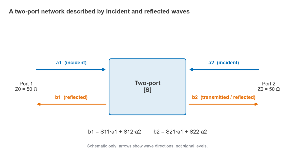
Every S-parameter is a complex number with a magnitude and a phase, and both depend on frequency. A Touchstone .s2p file lists four complex values per frequency point.
S11, S21, S12 and S22
- S11, input reflection coefficient. The fraction of the wave incident on port 1 that is reflected, with port 2 terminated in Z0. It equals Γin = (Zin − Z0)/(Zin + Z0). A small |S11| means a good input match.
- S21, forward transmission. The wave arriving at port 2 for a wave incident on port 1. |S21|2 is the transducer power gain between Z0 source and load. For an amplifier it is the gain; for a filter or cable it is the insertion loss, expressed as a negative number in dB.
- S12, reverse transmission. The wave leaking from port 2 back to port 1. For an amplifier, |S12| in dB is the reverse isolation, and a large value of isolation helps stability and keeps the LO in a receiver from reaching the antenna.
- S22, output reflection coefficient. The reflection seen looking into port 2 with port 1 terminated in Z0, which describes the output match.
Magnitudes are usually plotted in decibels using 20 log10|Sij|, because S-parameters are ratios of wave amplitudes rather than powers. The 20 log form still gives power ratios, since |b|2 and |a|2 are proportional to power. The difference between 10 log and 20 log is covered in dB, dBm, dBW and dBc explained.
When a two-port is not terminated in Z0, its input reflection changes. With a load reflection ΓL at port 2,
Γin = S11 + S12S21ΓL / (1 − S22ΓL)
This expression is the starting point for amplifier gain definitions and for stability analysis. Both are developed in power gain definitions and amplifier stability and the K-factor.
S11 in dB vs Return Loss vs VSWR
Three numbers describe the same input match, and confusing their signs is a common source of error.
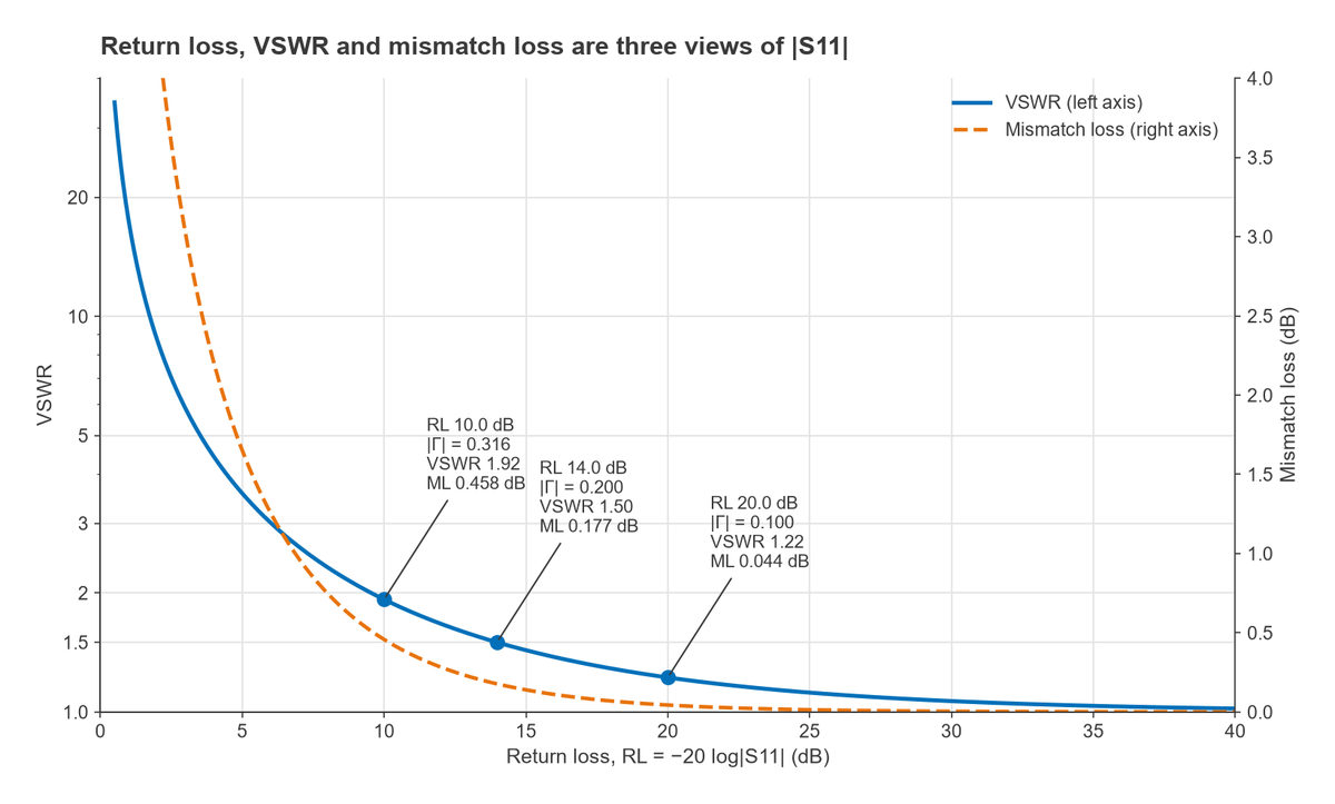
- |S11| in dB = 20 log10|S11|, a negative number for a passive port (for example −14 dB).
- Return loss RL = −20 log10|S11|, the same magnitude as a positive number (14 dB). A larger return loss means a better match.
- VSWR = (1 + |S11|)/(1 − |S11|), the ratio of maximum to minimum voltage on a line feeding the port.
The power lost to reflection, the mismatch loss, is ML = −10 log10(1 − |S11|2). The table gives common values.
| |S11| (dB) | Return loss (dB) | |Γ| | VSWR | Mismatch loss (dB) |
|---|---|---|---|---|
| −6 | 6 | 0.501 | 3.01 | 1.25 |
| −10 | 10 | 0.316 | 1.92 | 0.46 |
| −14 | 14 | 0.200 | 1.50 | 0.18 |
| −20 | 20 | 0.100 | 1.22 | 0.044 |
| −30 | 30 | 0.032 | 1.07 | 0.004 |
A 10 dB return loss, often quoted as a minimum for a usable match, reflects 10% of the incident power and costs 0.46 dB. Going from 10 dB to 20 dB return loss saves only about 0.41 dB of delivered power, which is why matching beyond 15 to 20 dB is usually done for filter flatness, cable ripple or measurement accuracy rather than for power. The VSWR, return loss and mismatch loss page includes a calculator, and the Smith chart shows S11 graphically.
Reciprocity, Losslessness and Symmetry
Reciprocity
A network built from linear, passive, isotropic materials (resistors, capacitors, inductors, transmission lines) is reciprocal: Sij = Sji, so the matrix equals its transpose. Filters, attenuators, couplers and cables are reciprocal. Amplifiers are not, since S21 may be +20 dB while S12 is −30 dB. Ferrite circulators and isolators are passive but non-reciprocal by design; see circulators and isolators.
Losslessness
A lossless network delivers all incident power to its ports, so its S-matrix is unitary: SHS = I, where SH is the conjugate transpose. For a two-port this requires |S11|2 + |S21|2 = 1 and |S12|2 + |S22|2 = 1. Any shortfall is power dissipated in the network.
Symmetry
If a reciprocal two-port looks the same from either end, it is symmetric and S11 = S22. A uniform transmission line, a symmetric pi attenuator and a filter with mirror-image element values are all symmetric. A symmetric reciprocal two-port is fully described by two complex numbers, S11 and S21.
Worked Examples
A series resistor between 50 Ω ports
For a series impedance Z between two ports of reference impedance Z0, port 1 sees Z + Z0 when port 2 is terminated, which gives
S11 = S22 = Z / (Z + 2Z0), S21 = S12 = 2Z0 / (Z + 2Z0)
With Z = 50 Ω and Z0 = 50 Ω, S11 = 50/150 = 0.333 (−9.54 dB) and S21 = 100/150 = 0.667 (−3.52 dB). The network is reciprocal and symmetric, as expected. It is not lossless: |S11|2 + |S21|2 = 1/9 + 4/9 = 0.556, so 44.4% of the incident power is dissipated in the resistor, 11.1% is reflected and 44.4% reaches the load.
A third-order Butterworth low-pass filter
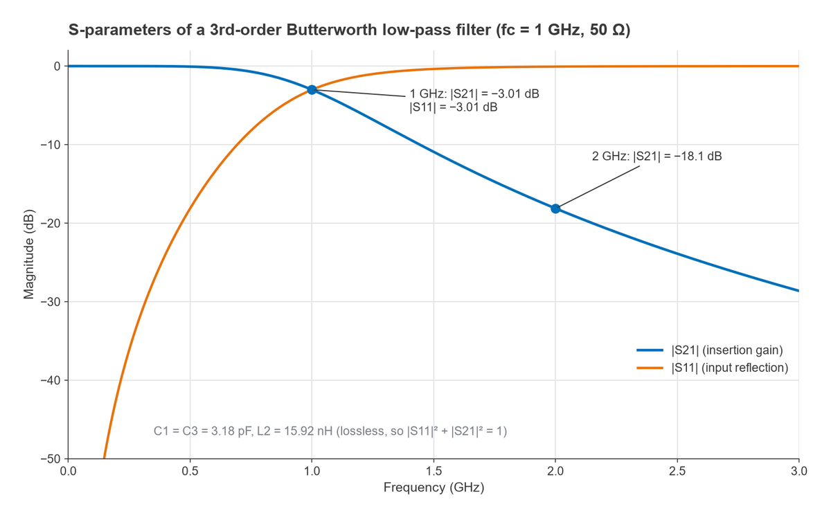
A 1 GHz, 50 Ω Butterworth low-pass filter with normalised values g1 = 1, g2 = 2, g3 = 1 uses shunt capacitors C = g/(2πfcZ0) = 3.18 pF and a series inductor L = gZ0/(2πfc) = 15.92 nH. Cascading the ABCD matrices of the three elements and converting to S-parameters gives:
- At 0.5 GHz: |S21| = −0.07 dB and |S11| = −18.1 dB.
- At 1 GHz: |S21| = |S11| = −3.01 dB, so half the power is transmitted and half reflected.
- At 2 GHz: |S21| = −18.1 dB, matching the Butterworth formula 10 log10(1 + 26) = 18.1 dB.
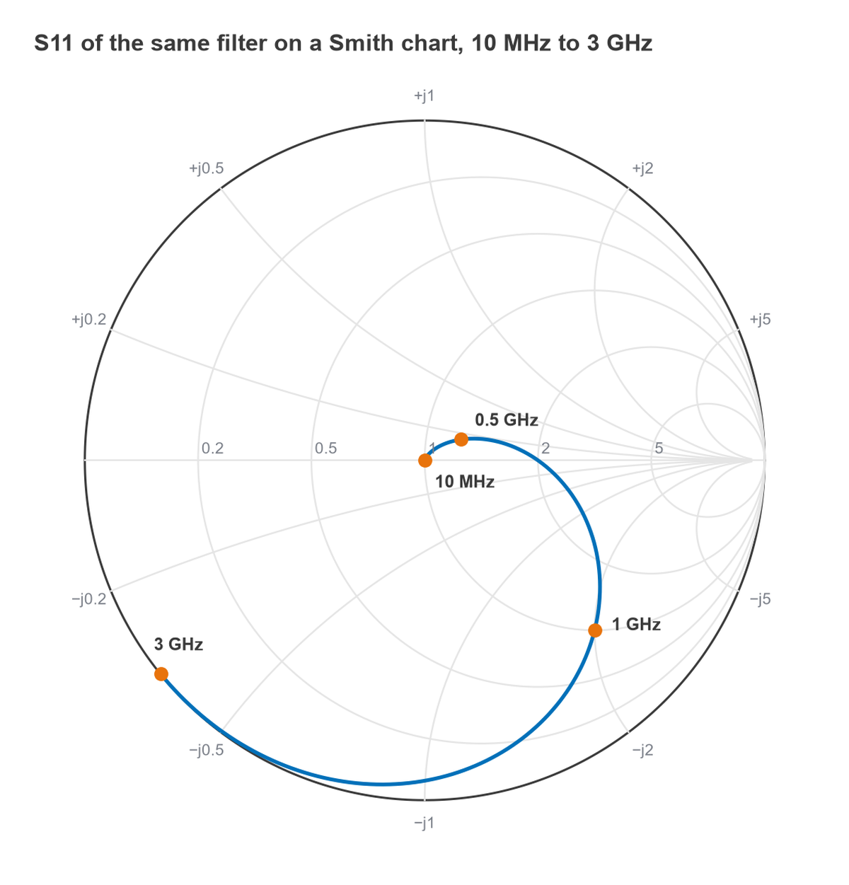
At 0.5 GHz, 10−1.81 + 10−0.0067 = 0.0154 + 0.9846 = 1.000, confirming the losslessness condition. A filter with real component Q would fall short of 1 by the fraction lost in the parts. On the Smith chart, S11 starts at the centre at low frequency and moves outward to the edge of the chart in the stopband, where nearly all power is reflected.
Why S-Parameters Instead of Z or Y Parameters
Z, Y, h and ABCD parameters describe the same linear network and can be converted to S-parameters and back. The preference for S-parameters at RF is practical:
- Z and Y parameters need open-circuit or short-circuit terminations. At high frequency a good open or short is hard to realise at the device’s reference plane, and the parasitic capacitance or inductance of the fixture changes the result.
- Many active devices oscillate when terminated in an open or short. A matched 50 Ω load keeps them stable during measurement.
- Incident and reflected waves can be separated with directional couplers and measured as power ratios, which is exactly what a network analyzer does.
- S-parameters map directly onto quantities engineers care about: gain, insertion loss, return loss and isolation.
How S-Parameters Are Measured
S-parameters are measured with a vector network analyzer (VNA). The instrument drives each port in turn from a swept source, separates the incident and reflected waves with directional couplers or bridges, and measures their ratio in magnitude and phase with coherent receivers. Before measurement the VNA is calibrated with known standards to remove the errors of its own couplers, cables and connectors, so that the result refers to a defined reference plane. Where the device sits in a test fixture, the fixture’s own response is removed afterwards by de-embedding. These steps are covered in VNA basics, VNA calibration and de-embedding. Differential circuits are characterised with mixed-mode S-parameters.
Frequently Asked Questions
What are S-parameters?
They are complex, frequency-dependent ratios of outgoing to incoming waves at the ports of a linear network, measured with all ports terminated in a reference impedance. They describe how much of a signal is reflected at each port and how much passes between ports.
What is S11 and S21?
S11 is the input reflection coefficient: the ratio of the reflected wave to the incident wave at port 1. S21 is the forward transmission coefficient: the wave arriving at port 2 relative to the wave incident on port 1. In dB, S11 shows the input match and S21 shows gain or insertion loss.
Why use S-parameters instead of Z or Y parameters?
Z and Y parameters need open and short terminations, which are difficult to create accurately at RF and can make active devices oscillate. S-parameters use matched loads, can be measured directly with a VNA, and correspond to gain, loss and match.
How are S-parameters measured?
With a calibrated vector network analyzer, which measures the magnitude and phase of reflected and transmitted waves at each port across frequency. Calibration and de-embedding move the reference plane to the device itself.
Related Topics
The next steps are power gain definitions, stability and the K-factor and Touchstone files. For background, see transmission lines and impedance matching and reflection and transmission coefficients. Noise parameters, which S-parameters do not include, are covered under noise in RF systems.