

RF design applications are the end uses, such as software-defined radio, IoT, GNSS, radar, satellite links and cellular networks, that take general radio-frequency techniques and turn them into specific products. RF design is used wherever information or energy travels wirelessly, and each application weights noise, linearity, power, phase noise, bandwidth and cost differently.
This hub is the applications section of the RF design guide. The rest of the site explains the building blocks: amplifiers, filters, mixers, oscillators and radio architectures. The pages listed here show how those blocks are combined and traded off for one job at a time.
Where RF Design Is Used
Every application starts from the same chain: antenna, filtering, amplification, frequency conversion or direct sampling, and data conversion. What changes is the frequency, the signal levels, the bandwidth and the constraints on size, power and cost. A GNSS receiver works with signals around −130 dBm, well below the thermal noise in its bandwidth, and lives or dies by noise figure. A 5G base station transmits wideband signals with high peak-to-average power ratio and is dominated by linearity and efficiency. A battery-powered IoT node gives up bandwidth and data rate to stretch range and battery life. An automotive radar at 77 GHz works where the free-space wavelength is about 3.9 mm, so antennas, packaging and interconnect become part of the circuit.
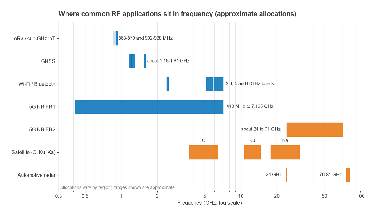
Frequency is the first thing that separates these applications. Sub-GHz IoT, GNSS and most cellular and Wi-Fi traffic sit below about 7 GHz, where printed circuit techniques and packaged parts work well. Satellite links, FR2 cellular and automotive radar move into the tens of gigahertz, where the mmWave radio architectures and beamforming and phased arrays parts of the Radio Architectures series apply.
Application Guides
Software-defined radio
- What is a software-defined radio? How an SDR moves filtering and demodulation into software, and what the RF front end must still do.
- Best software-defined radios: how to compare SDR hardware on tuning range, bandwidth, ADC resolution and front-end performance.
For the receiver theory behind wideband SDRs, see direct RF sampling and SDR architectures and the guide to choosing an LNA for SDR.
IoT and low-power wide-area networks
- LoRa network planning and RF site surveys: link budgets, gateway placement and field measurement for sub-GHz LPWAN deployments.
- RF energy harvesting: collecting power from ambient or dedicated RF sources with rectennas to run very low-power devices.
Small IoT products also face coexistence problems when several radios share one board, covered in RF coexistence.
Navigation and sensing
- GNSS receiver front-end design: active antennas, LNA noise figure, out-of-band rejection and protection from nearby cellular transmitters.
- Radar basics for RF engineers: pulse and FMCW radar, the radar equation, range resolution and the RF requirements they create.
Communications infrastructure
- 5G NR RF front-end design: FR1 and FR2 front ends, filtering, PA linearity and the shift to arrays at mmWave.
- Satellite communication RF design: G/T, EIRP, low-noise block converters and the satellite link budget.
Front-end integration for handsets and small cells is covered in RF front-end modules.
What Changes from One Application to the Next
The same specifications appear on every datasheet, but their weight changes. The matrix in this section is an editorial summary, not a measured result, and real projects vary. It shows the pattern most designers recognise.
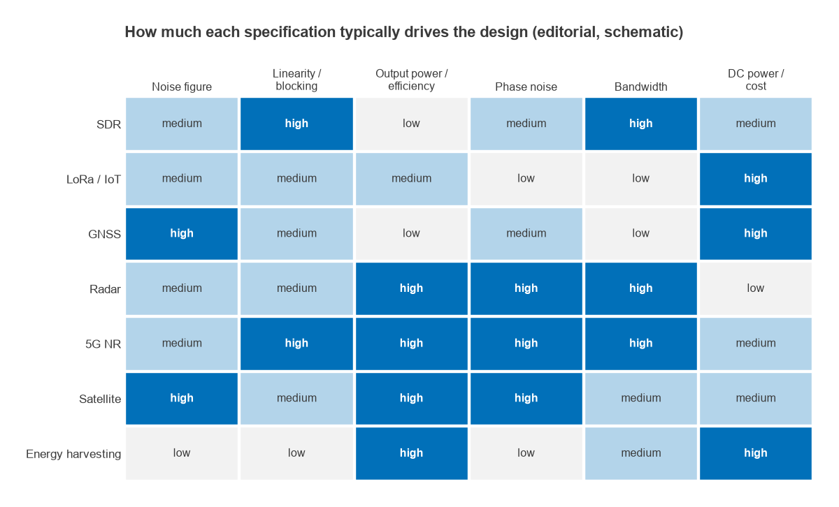
- Noise-limited applications such as GNSS and satellite ground terminals put the LNA as close to the antenna as possible and spend effort on receiver sensitivity and noise temperature.
- Linearity-limited applications such as cellular base stations and wideband SDRs must handle strong signals near weak ones, so blocking, intermodulation and dynamic range dominate.
- Power-limited applications such as radar transmitters and satellite uplinks centre on PA output power, efficiency and heat.
- Cost- and battery-limited applications such as IoT nodes and energy harvesters accept modest RF performance in exchange for low current and low bill of materials.
Whatever the application, the first sizing step is usually a link budget: transmit power, antenna gains, path loss and receiver sensitivity in one table. The RF link budget article explains the method, the link budget calculator automates it, and free-space path loss and antennas and propagation supply the path term.
Wavelength is the other quantity worth fixing early, because it sets antenna size and how much of the layout behaves as a transmission line. In free space it is about 345 mm at 868 MHz, 190 mm at the GPS L1 frequency of 1575.42 MHz, 86 mm at 3.5 GHz, 10.7 mm at 28 GHz and 3.9 mm at 77 GHz. Below a few gigahertz, lumped components and short traces behave predictably; at mmWave, every bond wire and via is a significant fraction of a wavelength.
Frequently Asked Questions
Where is RF design used?
In any system that sends or receives radio signals: mobile phones and base stations, Wi-Fi and Bluetooth, IoT sensors, GNSS receivers, radar, satellite terminals, broadcast, test equipment and software-defined radios. Wireless power and RF energy harvesting also rely on RF design.
Which RF application is hardest to design for?
There is no single answer. mmWave systems are hard because of packaging, loss and array calibration, while wideband receivers are hard because of linearity and spurious responses. The difficulty depends on which specification is pushed furthest.
Do the same building blocks apply to every application?
Yes. Amplifiers, filters, mixers, oscillators and data converters appear in nearly every radio. The application changes their specifications, the frequency and the trade-offs between them.
Related Topics
Start with the RF design pillar for the full map of the site, the Radio Architectures series for system-level background, and phased array design for the array techniques used in radar, 5G and satellite terminals.