

An RF mixer is a three-port circuit that shifts a signal from one frequency to another by multiplying it with a local oscillator (LO). Its output contains the sum and difference of the input and LO frequencies, and a filter keeps the one that is wanted. Mixers are what let a receiver process every channel at one fixed intermediate frequency, and let a transmitter build its signal at low frequency before moving it to the carrier.
This hub explains the principle that every mixer shares, the specifications used to compare them, and the problems that frequency conversion brings with it. It then links to the detailed pages in this branch of the RF design reference. Mixers in a full receiver chain are also covered in Radio Architectures Part 2: receivers, LOs and mixers.
What an RF Mixer Does: Multiplication
The core operation is multiplication. Feeding an RF signal cos(ωRFt) and an LO cos(ωLOt) into an ideal multiplier gives
cos(ωRFt) · cos(ωLOt) = ½cos((ωRF − ωLO)t) + ½cos((ωRF + ωLO)t)
The output contains only the difference frequency and the sum frequency, each with half the amplitude, or 6.02 dB below the product of the input amplitudes. Nothing remains at the RF or LO frequency. In a downconverter the difference is kept and called the intermediate frequency (IF); in an upconverter the sum, or sometimes the difference, is kept. Any modulation on the RF signal transfers unchanged to the IF, because the multiplication is linear in the RF input. That linearity is what separates a mixer from a simple nonlinear device such as a frequency multiplier.
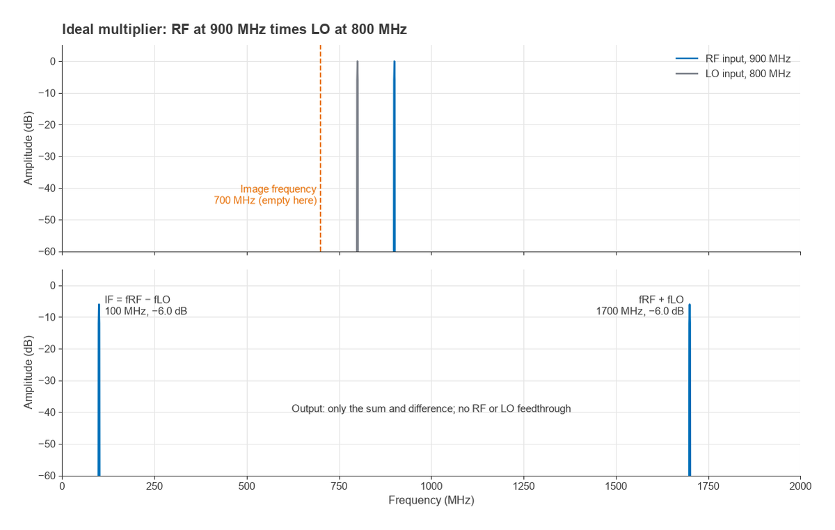
Take an RF signal at 900 MHz and an LO at 800 MHz. The output carries a 100 MHz IF and a 1700 MHz sum product, and a lowpass or bandpass filter after the mixer keeps the 100 MHz term.
The image frequency
The difference term depends only on |fRF − fLO|. With the LO at 800 MHz, a signal at 700 MHz also produces a 100 MHz output. This second input is the image frequency, fimage = 2fLO − fRF, and the mixer cannot tell it apart from the wanted signal. Any energy at the image must be removed before the mixer by filtering, or cancelled with an image-reject architecture. The choice of IF sets how far the image sits from the wanted band, and so how hard the preselect filter has to work. Image frequency and image-reject mixers covers both approaches.
Real Mixers Switch Rather Than Multiply
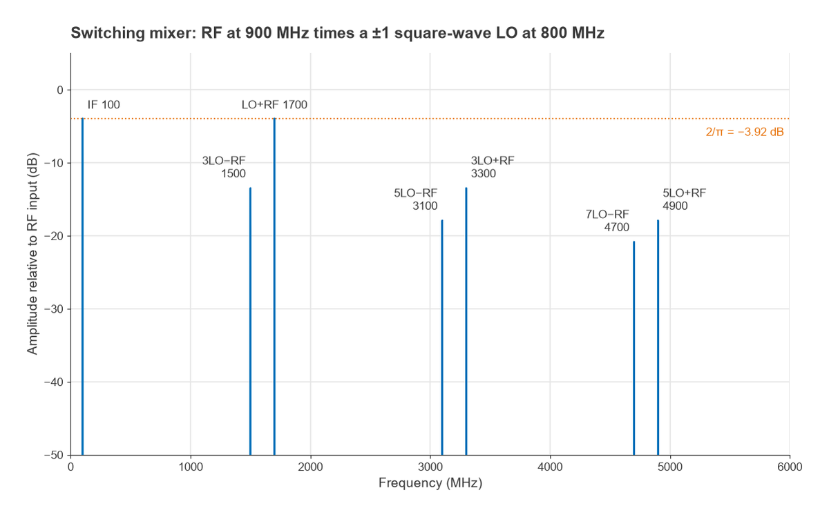
Accurate analog multipliers are hard to build at RF, so most practical mixers use the LO to switch the RF path on and off, or to reverse its polarity. A diode ring, a FET ring or the switching quad of a Gilbert cell all behave approximately as a multiplication by a square wave of amplitude ±1. A square wave contains the LO fundamental with amplitude 4/π and odd harmonics at 3fLO, 5fLO and above, falling as 1/n. Multiplying gives:
- The wanted IF and the sum product at an amplitude of 2/π relative to the RF input, a conversion loss of 3.92 dB. This is the textbook minimum for an ideal switching mixer that delivers one sideband to the load.
- Responses at 3fLO ± fRF, about 9.5 dB lower, and at 5fLO ± fRF, about 14 dB lower.
- The same harmonics also convert unwanted inputs near 3fLO ± fIF down to the IF, which creates additional spurious responses.
Real diodes and transistors add loss, imperfect switching and mismatch, so passive double-balanced mixers typically show conversion loss of roughly 5 to 7 dB. Balancing the structure cancels many even-order products and suppresses RF and LO feedthrough at the IF port. Single-, double- and triple-balanced rings and the Gilbert cell are compared in mixer types.
Mixer Specifications
A mixer datasheet uses the same quantities as an amplifier, plus a few that apply only to three-port devices:
| Parameter | What it measures |
|---|---|
| Conversion gain or loss | IF output power relative to RF input power, in dB |
| Noise figure | Added noise, usually quoted single-sideband; for a passive mixer it is close to the conversion loss |
| IIP3 and P1dB | Third-order intercept and compression at the RF input, see intermodulation and intercept points |
| LO drive level | LO power the mixer needs to switch fully; passive diode mixers are often specified for drive levels such as +7, +13 or +17 dBm |
| Isolation | LO-to-RF, LO-to-IF and RF-to-IF leakage, in dB |
| Spurious responses | Level of m × n products, often given as a table relative to the IF output |
Because the mixer sits between the low-noise front end and the IF chain, its noise figure and linearity both enter the cascade. With an LNA of 15 dB gain in front, a mixer noise figure of 7 dB contributes (100.7 − 1)/101.5 = 0.13 in linear noise factor; that small contribution is the reason receivers put gain ahead of the mixer. The trade-off is that the same LNA gain raises the signal level at the mixer and makes its IIP3 more critical. The calculation is covered in cascaded noise figure and cascaded IP3.
Topics in This Section
- Mixer Types: Single, Double, Triple-Balanced and Gilbert Cell: topologies, port isolation, LO drive and where each is used.
- Image Frequency and Image-Reject Mixers: why the image appears and how Hartley and Weaver architectures cancel it.
- IQ Modulators and Demodulators: quadrature mixers, amplitude and phase imbalance, and their effect on sideband suppression and EVM.
- Frequency Planning and Spur Charts: choosing IF and LO frequencies so that m × n products fall outside the band.
The LO itself comes from the oscillators and frequency synthesis section; its phase noise transfers directly onto the converted signal, a process called reciprocal mixing. Receiver architectures that avoid a conventional IF, such as zero-IF and low-IF receivers, still depend on mixers but move the problems to DC offset, IQ balance and second-order distortion.
Frequently asked questions
What does an RF mixer do?
It multiplies an input signal by a local oscillator, producing outputs at the sum and difference of the two frequencies. A filter selects one of them, so the signal and its modulation are moved to a new frequency. Receivers use mixers to downconvert to an IF or baseband, and transmitters use them to upconvert to the carrier.
Why does a mixer have conversion loss?
Even an ideal mixer splits the input power between the sum and difference products, and a switching mixer also spreads some power into harmonic products. An ideal switching mixer therefore has 3.92 dB of loss to one sideband. Diode and FET resistance, mismatch and imperfect switching add more.
Is a mixer a linear or nonlinear device?
Ideally it is linear with respect to the RF signal and time-varying because of the LO. Doubling the RF input doubles the IF output, which is why modulation is preserved. Real mixers are also weakly nonlinear in the RF path, so they have compression and intercept points just like amplifiers.
Related topics
Mixers sit inside every transmitter architecture and receiver lineup. Their behaviour is characterized with the same tools as other RF blocks: S-parameters at each port, linearity measurements and noise figure. The underlying signal theory is in RF fundamentals, and terms such as IF, image and LO are defined in the wireless terms glossary.