

An RF amplifier is an active circuit that increases the power of a radio-frequency signal while keeping its waveform as intact as the application requires. The main types are low-noise amplifiers (LNAs), gain blocks, broadband amplifiers, drivers, power amplifiers (PAs) and distributed amplifiers, and they differ mainly in which specification each one is optimised for: noise figure, flat gain, bandwidth, linearity or output power and efficiency.
Amplifiers appear in every branch of RF design, from the first stage behind a receive antenna to the last stage before a transmit antenna. This hub sorts them by role, explains the datasheet terms used to compare them, and links to the detailed design and selection pages in this section.
Types of RF Amplifier
The same transistor technologies are used across all of these types. What separates them is the design target, the matching networks around the device and the bias point.
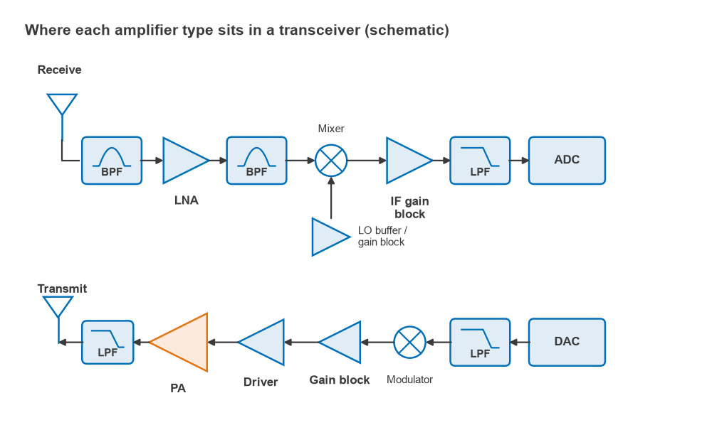
- Low-noise amplifier (LNA). The first active stage in a receiver. It is matched for minimum noise figure rather than maximum gain, and its noise figure largely sets the sensitivity of the whole receiver.
- Gain block. A cascadable, internally matched amplifier, typically a 50-ohm MMIC with resistive feedback, used wherever moderate gain is needed with little design effort: IF strips, LO chains, instrument paths.
- Broadband amplifier. Any amplifier designed for flat gain over an octave or more. Many gain blocks are broadband; connectorized broadband amplifiers are common bench tools.
- Driver amplifier. The stage that raises a transmit signal to the level a power amplifier needs. Its linearity matters almost as much as the PA’s, because its distortion is amplified with the signal.
- Power amplifier (PA). The final transmit stage, designed for output power and efficiency, with linearity traded against both through the choice of class and linearization.
- Distributed (traveling-wave) amplifier. Several transistors share artificial transmission lines at input and output, so their capacitances become part of the lines. This gives gain over very wide bandwidths, often several octaves, at the cost of efficiency.
Distributed amplifiers do not have a fixed position in a radio. They appear where a single stage must cover a multi-octave band, for example in instrumentation, optical-link drivers and wideband test front ends.
Datasheet Specifications at a Glance
| Specification | What it describes | Most important for |
|---|---|---|
| Gain (S21) | Small-signal power gain in dB at the stated frequency, bias and temperature | All types |
| Gain flatness | Peak-to-peak gain variation across the band | Broadband amplifiers, gain blocks |
| Noise figure (NF) | Degradation of signal-to-noise ratio through the stage | LNAs |
| P1dB | Power level where gain has dropped by 1 dB | Drivers, PAs, gain blocks |
| OIP3 / IIP3 | Third-order intercept, a measure of intermodulation | LNAs in crowded bands, drivers, gain blocks |
| Psat | Maximum output power | PAs |
| PAE / drain efficiency | Fraction of DC power converted to RF output | PAs |
| Input/output return loss or VSWR | Quality of the 50-ohm match | Gain blocks, broadband amplifiers |
| Reverse isolation (S12) | How much signal leaks backwards through the stage | LO buffers, LNAs |
| Stability factor (K, μ) | Whether the amplifier can oscillate for some source or load | All types |
| Supply voltage and current | DC operating point and power draw | Battery and mast-mounted equipment |
The linearity entries are explained in the linearity and distortion section, especially P1dB and gain compression. Noise figure is covered in the noise figure article, and gain definitions and stability in the S-parameters section.
Which Specification Matters Most
The answer depends on where the amplifier sits. Early stages set the noise floor; late stages set the distortion limit. Consider a receive chain made of an LNA (18 dB gain, 1 dB NF, IIP3 +10 dBm), a filter with 2 dB loss, a gain block (15 dB gain, 4 dB NF, IIP3 +18 dBm) and a mixer (7 dB conversion loss, 9 dB NF, IIP3 +15 dBm). The Friis formula gives a cascaded noise figure of 1.18 dB, and the LNA accounts for 83 percent of the excess noise. The cascaded IIP3 is −16.1 dBm, and the mixer accounts for 98 percent of it, because 31 dB of gain sits in front of it.
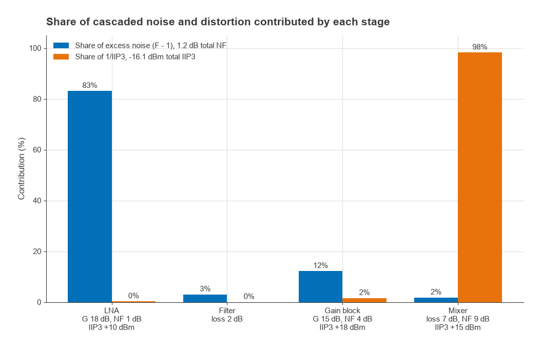
So for the LNA, noise figure matters most, and for later stages, intercept point matters most. Removing the gain block in this example would raise the cascaded IIP3 by about 15 dB, to −1.3 dBm, while the noise figure rises only from 1.18 dB to 1.59 dB, which is often the better trade in a strong-signal environment. Placement and level planning are covered in How to Choose an LNA and in the cascaded noise figure calculator.
Pages in This Section
Low-noise and broadband amplifiers
- Low Noise Amplifier (LNA) Design: noise matching, gain and stability for the first receive stage.
- How to Choose an LNA: Specs That Matter: noise figure, gain, IP3, placement and filtering decisions.
- LNA Setup for SDR, ADS-B, GNSS and Weak-Signal Receivers: practical front ends for software-defined radio.
- Broadband RF Amplifier Design: feedback, Darlington and balanced topologies for flat gain.
- How to Choose a Broadband RF Amplifier / Gain Block: bandwidth, flatness, P1dB, VSWR and packaging choices.
- Distributed (Traveling-Wave) Amplifiers: how multi-octave gain is achieved.
Specifications, biasing and devices
- LNA vs Gain Block vs Power Amplifier: a side-by-side comparison of the three main roles.
- How to Read an RF Amplifier Datasheet: test conditions, typical versus guaranteed values and hidden assumptions.
- Biasing RF Transistors and MMICs: bias tees, chokes and stable operating points.
- RF Transistor Technologies: GaAs, GaN, SiGe, LDMOS and CMOS compared.
Power amplifiers
- Power Amplifier Classes and Efficiency: Radio Architectures Part 7, classes A through F and switching modes.
- PA Linearization: Feedforward, DPD, Doherty: Radio Architectures Part 8.
- Power Amplifier Design and Load-Pull: choosing the load impedance for power and efficiency.
- Thermal Design for RF Power Amplifiers: junction temperature, heat sinks and reliability.
Frequently asked questions
What are the types of RF amplifiers?
By role, the main types are low-noise amplifiers, gain blocks, broadband amplifiers, driver amplifiers, power amplifiers and distributed amplifiers. Power amplifiers are further divided by class (A, AB, B, C, D, E, F and others) according to how the transistor is biased and driven.
Which RF amplifier spec matters most?
It depends on the amplifier’s position. For the first receive stage, noise figure dominates. For later receive stages and for drivers, IP3 and P1dB dominate. For the final transmit stage, output power and efficiency come first, subject to the linearity the modulation requires.
Can one amplifier serve as both an LNA and a gain block?
Sometimes. A gain block with a noise figure of a few dB works as a first stage when the antenna noise is already high, as in many HF and VHF systems. Where the antenna sees a cold sky or the cable loss is low, a dedicated LNA with a lower noise figure gives a measurable sensitivity improvement.
Related topics
Amplifier design draws on impedance matching, stability analysis and the receiver lineups worked through in Radio Architectures Part 4. Definitions of the terms above are also collected in the wireless terms glossary.