

An LNA for an SDR is a low-noise preamplifier placed ahead of the receiver to set the system noise figure before cable loss and the SDR’s own front end can degrade it. Whether you need one depends on three things: how much loss sits between antenna and radio, how noisy the SDR is compared with the antenna’s noise, and how strong the off-channel signals are. ADS-B, GNSS and L-band satellite reception usually benefit; HF reception usually does not.
This page is a decision guide for weak-signal receive setups built around a software-defined radio. It sits under RF amplifiers and complements the general LNA selection guide.
Does an SDR need an LNA?
The answer comes from the Friis formula for cascaded noise factor, with every quantity in linear units:
Ftotal = F1 + (F2 − 1)/G1 + (F3 − 1)/(G1G2) + …
A passive cable of loss L has a noise factor equal to L and a gain of 1/L. Put a lossy cable first and its loss adds directly to the noise figure. Put an LNA with enough gain first and the cable and SDR contributions are divided by that gain. Low-cost SDRs are wideband designs whose noise figure is often several decibels, so a good LNA at the antenna can buy a large improvement. A well-designed receiver with a short cable gains little.
Worked example: ADS-B at 1090 MHz with 5 dB of cable
Assume an SDR with a noise figure of 6 dB (F = 3.98), a coax run with 5 dB of loss at 1090 MHz (L = 3.16), and an LNA with a noise figure of 0.8 dB (F = 1.20) and 20 dB of gain (G = 100). These are illustrative values, not measurements of a particular product.
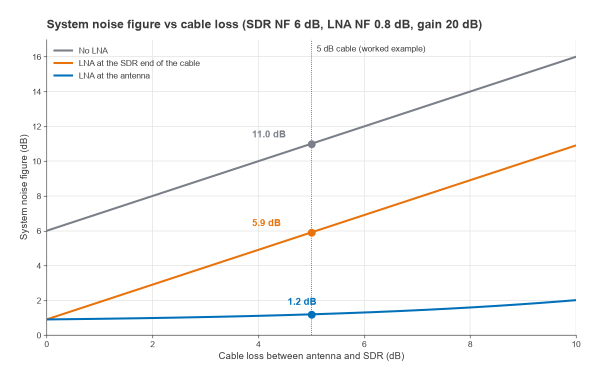
- No LNA: F = 3.16 × 3.98 = 12.6, so NF = 11.0 dB. Cable loss and SDR noise figure simply add.
- LNA at the SDR end of the cable: F = 3.16 × (1.20 + 2.98/100) = 3.90, so NF = 5.9 dB. The LNA hides the SDR but cannot recover the 5 dB already lost in the cable.
- LNA at the antenna: F = 1.20 + 2.16/100 + 2.98/(100/3.16) = 1.32, so NF = 1.2 dB.
Noise figure is not the whole story, because the antenna also delivers noise. Converting to noise temperature, Te = 290(F − 1), gives 3361 K, 840 K and 92 K for the three cases. With an antenna temperature of 290 K, typical of a low-elevation antenna that sees the warm ground and horizon, system temperatures are 3651 K, 1130 K and 382 K. The mast LNA therefore improves signal-to-noise ratio by 10 log(3651/382) = 9.8 dB, and the receiver-end LNA by 5.1 dB. For a sky-facing GNSS or satellite antenna with an antenna temperature nearer 100 K, the mast LNA gains about 12.6 dB.
Nearly 10 dB of SNR is roughly a factor of three in free-space range, which is why the mast LNA is the standard upgrade for ADS-B feeders.
When an LNA does not help
Below about 30 MHz the antenna noise is dominated by atmospheric, galactic and man-made noise, which is typically tens of decibels above kTB. Suppose the external noise is 30 dB above kTB (Fa = 1000) and the SDR has a 10 dB noise figure. The SNR penalty from the receiver is 10 log((1000 + 9)/1000) = 0.04 dB. Even a 15 dB noise figure costs only 0.13 dB. An LNA at HF adds gain, and therefore overload risk, without improving sensitivity. A simple test: if the noise floor rises by more than a few decibels when the antenna is connected, the receiver is already sensitive enough.
Use-case matrix
The table summarises typical choices. Noise figure and gain targets are typical ranges, not requirements, and the right answer depends on cable length and the local RF environment.
| Application | Frequency | LNA worthwhile? | Placement and filtering | Main threat |
|---|---|---|---|---|
| ADS-B | 1090 MHz | Usually yes, especially with long cable runs | At the antenna; filtered LNA with a 1090 MHz SAW or cavity filter; NF below about 1 dB, gain 15 to 25 dB | Cellular, paging and FM broadcast overload; nearby DME/TACAN in the 960 to 1215 MHz band |
| GNSS L1/E1 | 1575.42 MHz | Usually built into active antennas | At the antenna; typical active antennas have a filtered LNA with 25 to 40 dB gain, powered over the coax | Strong nearby cellular and L-band transmitters; too much gain into a receiver that expects a passive antenna |
| GNSS L5/E5a | 1176.45 MHz | Yes, same reasoning as L1 | At the antenna; filter must pass L5 and reject aeronautical pulses in the same band | DME/TACAN pulse interference |
| Satellite L-band (weather, Inmarsat, Iridium) | Roughly 1.5 to 1.7 GHz | Yes for small dishes and patch antennas | At the feed; filtered LNA with NF well below 1 dB | Adjacent cellular bands, 4G/5G base stations |
| VHF weather satellites | Around 137 MHz | Sometimes | At the antenna, with an FM broadcast notch or bandpass before the LNA | FM broadcast at 88 to 108 MHz |
| HF | 3 to 30 MHz | Rarely | Attenuation and filtering usually help more than gain | AM broadcast and strong amateur signals |
Where the LNA goes
Figure 1 shows the three configurations from the worked example across cable losses from 0 to 10 dB. The no-LNA case rises one decibel per decibel of cable loss. The receiver-end LNA removes the SDR’s contribution but still rises one for one. The mast-mounted LNA stays near its own noise figure until cable loss approaches the LNA gain. With 20 dB of LNA gain and 10 dB of cable, the system noise figure is still only about 2 dB.
A filter on the antenna side of the LNA adds its loss directly to the noise figure: 1 dB of filter loss ahead of a 0.8 dB LNA gives at least 1.8 dB. Filtered LNAs therefore either use a very low-loss first filter or split the filtering around the first gain stage. The LNA design article covers the first-stage trade-offs.
Bias-tee powering
A mast LNA needs DC, and running a separate power cable up the mast is awkward. A bias tee puts DC on the centre conductor of the same coax that carries the RF. At the receiver end, an inductor (the RF choke) feeds DC onto the line while presenting a high impedance to RF, and a series capacitor blocks DC from reaching the SDR input. At the LNA end, a matching choke takes the DC off and a capacitor keeps it out of the antenna.
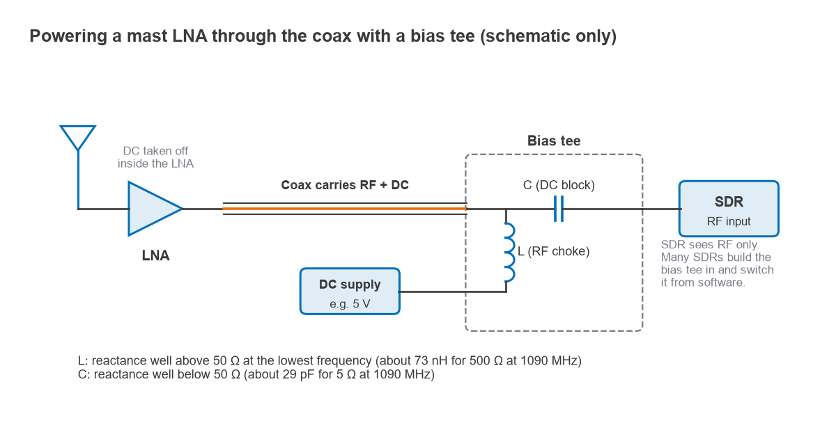
The component values follow from reactance. The choke should present an impedance much higher than 50 Ω at the lowest operating frequency. For 500 Ω at 1090 MHz, L = X/(2πf) = 500/(2π × 1.09 × 109) = 73 nH. The blocking capacitor should present much less than 50 Ω; for 5 Ω at the same frequency, C = 1/(2πfX) = 29 pF. The choke’s self-resonant frequency must be above the band of interest, or it will look capacitive and load the line.
Many SDRs and GNSS receivers include a bias tee that can be switched on from software or a jumper. Before relying on one, check four points:
- Voltage and current. The LNA’s supply range must include the bias-tee voltage, and its current draw must sit within what the SDR can supply. Built-in bias tees are usually low-current supplies.
- Voltage drop. The drop along the coax is V = I × Rloop. An LNA drawing 60 mA through 1.5 Ω of loop resistance loses 0.09 V, which matters only for marginal supplies or very long runs.
- DC paths. A DC-shorted antenna, such as a folded dipole or some loop and ground-plane designs, will short the supply unless the LNA blocks DC at its input. Splitters, filters and some attenuators also block or short DC.
- Other equipment. Never connect a powered line to test equipment or another receiver that is not DC-blocked.
Overload risk near FM and cellular transmitters
An unfiltered wideband LNA amplifies everything the antenna delivers. Near an FM broadcast site or a cellular base station, the total power at the LNA can push the LNA, or the SDR behind it, into compression. The result is a raised noise floor, spurious signals across the spectrum and lost weak signals: the receiver looks deaf even though the LNA has a good noise figure. The mechanisms are covered in detail on receiver blocking and desensitization.
Worked example: an FM transmitter 5 km away
Take a 10 kW ERP FM transmitter at 98 MHz. ERP is referenced to a half-wave dipole, so EIRP = 70 dBm + 2.15 dB = 72.15 dBm. The free-space path loss at 5 km is 20 log(5) + 20 log(98) + 32.44 = 86.4 dB. With a 0 dBi antenna response at 98 MHz the received level is about −14 dBm. Free space is an upper bound; terrain and clutter usually reduce it, but a line-of-sight rooftop can approach it.
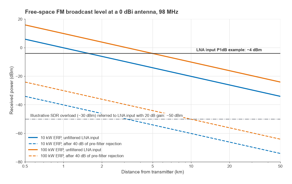
Consider an example LNA with 20 dB gain and an output P1dB of +15 dBm, so its input P1dB is about −4 dBm. The LNA itself is not compressed at −14 dBm, but its output is −14 + 20 = +6 dBm of FM power. If the SDR, with its gain set high, overloads at an illustrative −30 dBm, that point referred to the LNA input is −50 dBm, and the FM signal is 36 dB above it. Turning down the SDR gain helps only partly.
Figure 3 plots the free-space level against distance for 10 kW and 100 kW transmitters. Without filtering, both exceed the illustrative SDR overload level everywhere out to 50 km. With 40 dB of rejection at 98 MHz from a filter before the LNA, the 10 kW case falls below that level beyond about 3.2 km and the 100 kW case beyond about 10 km. Bandpass filters for ADS-B, GNSS and L-band, often SAW or BAW types, typically reject distant bands such as FM by much more than this; the harder cases are cellular signals only tens of megahertz away from the wanted band.
In practice, choose a filtered LNA for any single-band setup, add an FM notch for VHF reception near broadcast sites, and set LNA gain roughly 10 to 15 dB above the cable loss; beyond that, gain only reduces dynamic range. The broadband amplifier page discusses when an unfiltered wideband amplifier is still the right choice. After installation, the noise floor should rise when the LNA is powered, but the spectrum should not fill with spurious signals.
Frequently asked questions
Do I need an LNA for my SDR?
Above roughly 100 MHz with more than a couple of decibels of cable loss, an LNA at the antenna usually improves SNR noticeably. With a short cable and a quiet receiver, the gain is small. At HF, external noise dominates and an LNA rarely helps.
What is the best LNA for ADS-B at 1090 MHz?
A filtered LNA with a 1090 MHz bandpass filter, a noise figure below about 1 dB and moderate gain, mounted at the antenna. The filter matters as much as the noise figure, because cellular and broadcast signals are the most common cause of poor ADS-B range near towns.
How do I power an LNA via bias tee?
Enable the SDR’s built-in bias tee or insert an external bias tee between the coax and the SDR, then feed DC onto the coax. The LNA must accept that voltage on its RF input or output port. Check current limits and make sure nothing else on the line shorts or blocks the DC.
Related topics
For selection criteria in general, see how to choose an LNA. GNSS receivers are covered in GNSS front-end design, satellite links in satellite RF design, and wideband SDR receivers in Radio Architectures Part 13: direct RF sampling. Terms used here are defined in the wireless terms glossary.