

Q factor, or quality factor, is a dimensionless measure of how little energy a resonant circuit or reactive component loses relative to the energy it stores, defined as 2π times the peak stored energy divided by the energy dissipated per cycle. In RF design a high Q means low loss and, for a resonator, a narrow bandwidth, since Q also equals the centre frequency divided by the 3 dB bandwidth.
Q appears everywhere in RF work. It sets the loss of filters and matching networks, the selectivity of a tuned amplifier, the phase noise of an oscillator and the bandwidth of an antenna. The same word is used for an individual inductor or capacitor, for a complete resonator, and for a resonator once it is connected to its source and load, and the distinctions between those meanings matter. This page sits in the RF fundamentals section of the RF design reference.
Definitions of Q
The general definition applies to any system that stores and dissipates energy:
Q = 2π × (peak energy stored) / (energy dissipated per cycle) = ω0Wstored / Ploss
For a resonator this is equivalent to the bandwidth definition:
Q = f0 / BW3dB
where BW3dB is the width of the resonance between its half-power points. The two definitions agree exactly for a simple series or parallel RLC circuit, and closely for other resonators once Q is above about 10. For a series RLC circuit, Q = (1/R)√(L/C) = ω0L/R. For a parallel RLC circuit the resistance appears the other way up, Q = R√(C/L) = R/(ω0L), because a large parallel resistance draws little current and so wastes little energy.
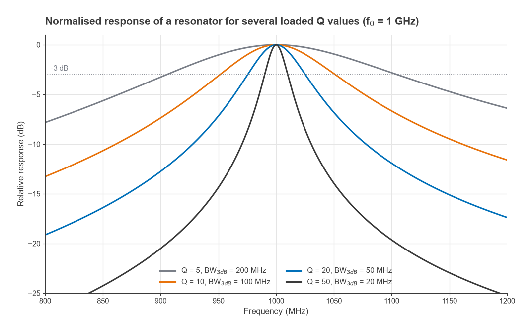
A resonator with Q = 20 at 1 GHz has a 3 dB bandwidth of 50 MHz. With Q = 50 the bandwidth shrinks to 20 MHz, and with Q = 5 it widens to 200 MHz. Figure 1 shows how the response sharpens as Q rises.
Component Q of inductors and capacitors
A single reactive component also has a Q, defined as the ratio of its reactance to its series resistance:
- Inductor: QL = ωL / Rs
- Capacitor: QC = 1 / (ωC × ESR)
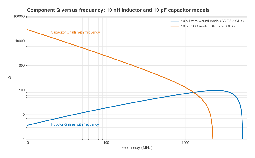
These two behave in opposite ways with frequency. Inductor reactance grows in proportion to f, while series resistance grows only as √f once skin effect sets in, so inductor Q rises with frequency until the part approaches its self-resonant frequency, where it collapses to zero. Capacitor reactance falls with frequency while ESR rises slowly, so capacitor Q falls steadily, and also reaches zero at self-resonance. Figure 2 shows both effects for a 10 nH wire-wound inductor model and a 10 pF C0G capacitor model: the inductor reaches Q of 71 at 1 GHz, while the capacitor falls from about 2400 at 100 MHz to about 130 at 1 GHz. The parasitics that cause the collapse are covered on the component parasitics page.
As a rough guide, chip inductors at a few hundred megahertz to a few gigahertz usually have Q somewhere between about 20 and 100, and good C0G capacitors have Q in the hundreds or higher over the same range. That is why inductors usually limit the Q of lumped resonators. Distributed and mechanical resonators reach far higher values: printed microstrip resonators are often in the low hundreds, ceramic coaxial resonators several hundred to around a thousand, metal cavities several thousand, and quartz crystals tens of thousands or more. These ranges are approximate and depend strongly on frequency, size and construction.
Combining component Q
When an inductor and capacitor form a resonator, their losses add. The losses are in parallel in terms of 1/Q:
1/Qu = 1/QL + 1/QC
The result is called the unloaded Q, Qu, because it describes the resonator on its own with nothing connected to it. The lower of the two component Q values dominates.
Loaded versus unloaded Q
A resonator is useful only once it is coupled to something. The source and load resistances also remove energy from it each cycle, and their effect is described by an external Q, Qe. The loaded Q, QL, combines both:
1/QL = 1/Qu + 1/Qe
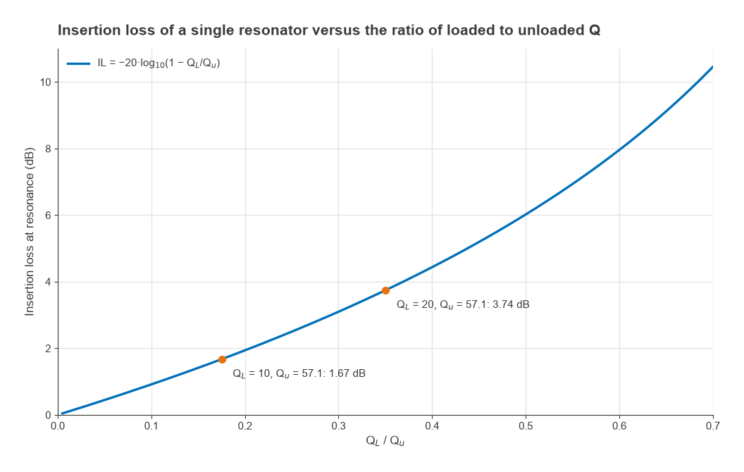
The loaded Q sets the bandwidth the circuit actually shows, BW = f0/QL. The unloaded Q sets how much of the signal is lost as heat. Energy delivered to the load is useful, energy dissipated in Qu is not, and the ratio between them depends on QL/Qu. For a single resonator coupled equally to source and load, the transmission at resonance is S21 = 1 − QL/Qu, so
IL = −20log10(1 − QL/Qu) dB
Asking for a narrow bandwidth means asking for a high QL. If QL approaches Qu, almost all the energy is dissipated inside the resonator and insertion loss becomes very large. This is the basic trade-off of every narrowband filter and the reason filter insertion loss scales inversely with fractional bandwidth.
Worked example: a 1 GHz LC resonator
A resonator uses a 10 nH inductor with 1.0 Ω series resistance at 1 GHz and a capacitor tuned to resonance with 0.1 Ω ESR.
- Capacitance for resonance: C = 1/(ω02L) = 1/((2π × 109)2 × 10⁻⁸) = 2.533 pF.
- Inductor Q: QL = ω0L/Rs = 62.83 / 1.0 = 62.8.
- Capacitor Q: QC = 1/(ω0C × ESR) = 62.83 / 0.1 = 628.
- Unloaded Q: 1/(1/62.8 + 1/628) = 57.1. The same value comes from (1/R)√(L/C) with R = 1.1 Ω.
If the resonator is coupled for QL = 10, the bandwidth is 1000/10 = 100 MHz and the insertion loss is −20log(1 − 10/57.1) = 1.67 dB. If the coupling is reduced for QL = 20, the bandwidth halves to 50 MHz but the loss rises to 3.74 dB. Pushing to QL = 40 for a 25 MHz bandwidth would cost 10.5 dB. A circuit simulation of the same resonator returns 1.672 dB and 3.744 dB, with bandwidths of exactly 100 and 50 MHz. The only way to get a narrow bandwidth with low loss is a higher Qu, which here means a better inductor.
Q in matching networks
Matching networks have a Q of their own. For an L-network matching Rhigh to Rlow, the network Q is fixed by the ratio, Q = √(Rhigh/Rlow − 1). Matching 50 Ω to 5 Ω gives Q = 3, and a bandwidth of very roughly f0/Q. Pi and T networks let the designer choose a higher Q for more selectivity or harmonic rejection. In both cases, the network’s loss rises with the ratio of its loaded Q to the component Q, by the same mechanism as in a filter. A high-ratio match built from low-Q inductors can lose a surprising fraction of a dB.
Q in oscillators
The resonator in an oscillator acts as a filter around the frequency of oscillation. A higher loaded Q gives a steeper phase slope, so a given noise disturbance produces a smaller frequency fluctuation. Leeson’s model expresses this: within the resonator bandwidth, the close-in phase noise falls by 20log10(QL) dB, so doubling QL improves it by about 6 dB in that region. This is why low-noise references use quartz crystals, why TCXOs and OCXOs are built around them, and why VCO design pays close attention to varactor and inductor Q.
Measuring Q
Q is usually measured with a vector network analyzer. For a resonator, the 3 dB bandwidth of a weakly coupled transmission measurement gives QL, and the insertion loss at resonance gives the coupling, from which Qu follows using the relationship above. Weak coupling keeps QL close to Qu, which is why resonator Q tests use very loose coupling. For individual components, Q comes from the measured impedance, Im(Z)/Re(Z), on a calibrated fixture. Fixture loss and pad parasitics are a common source of error, since they add resistance that the component itself does not have.
Frequently asked questions
What is Q factor?
Q factor is the ratio of energy stored to energy lost per cycle, multiplied by 2π. For a component it equals reactance divided by series resistance. For a resonator it also equals centre frequency divided by 3 dB bandwidth, so higher Q means both lower loss and a narrower response.
How does Q affect filter bandwidth?
A resonator’s bandwidth is f0/QL, so loaded Q sets the bandwidth directly. Unloaded Q limits how narrow the bandwidth can be made: as QL approaches Qu, insertion loss grows rapidly. Narrow, low-loss filters therefore need resonators with high unloaded Q.
What is the difference between loaded and unloaded Q?
Unloaded Q describes the resonator’s own losses with nothing attached. Loaded Q includes the energy taken by the source and load, and is always lower. Loaded Q sets the working bandwidth; the ratio of loaded to unloaded Q sets the insertion loss.
Is a higher Q always better?
Higher unloaded Q is almost always better because it means lower loss. Higher loaded Q is a design choice: it gives more selectivity and lower oscillator phase noise, but a narrower bandwidth, more sensitivity to component tolerance and temperature, and longer group delay.
Related topics
Q links the component level, covered in parasitics of passive components, with filter performance in RF filter specifications and LC filter design. Decibel conversions used on this page are explained in dB, dBm and dBc, and short definitions are collected in the wireless terms glossary.