

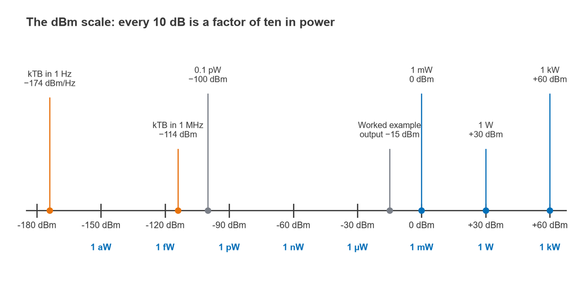
dBm is a logarithmic unit of absolute power referenced to one milliwatt: P(dBm) = 10 log10(P / 1 mW). To convert dBm to watts, use P(W) = 10(dBm − 30)/10, so 0 dBm is 1 mW, +30 dBm is 1 W and −30 dBm is 1 µW. The plain dB, by contrast, is a ratio with no reference, and dBW and dBc change only the reference point.
Decibels are the working language of RF design. Gains, losses, noise levels, spur levels and link margins are all expressed in them, and once the reference behind each variant is clear the arithmetic reduces to addition and subtraction. This page defines each unit, gives a conversion table and a converter, explains the difference between power and voltage decibels, and works through a cascade of gains and losses. It belongs to the RF fundamentals section of the RF design guide.
The Decibel as a Ratio
A decibel expresses the ratio of two powers on a logarithmic scale:
Ratio (dB) = 10 log10(P2 / P1)
Doubling power adds 10 log10(2) = 3.01 dB, a factor of ten adds 10 dB, and a factor of one thousand adds 30 dB. Halving power subtracts 3.01 dB. Because the logarithm of a product is the sum of the logarithms, a chain of gains and losses that would be multiplied as linear ratios is simply added in decibels. That property, together with the enormous dynamic range of radio signals, is why RF engineers use decibels almost exclusively.
A bare “dB” never describes an absolute level. An amplifier has 20 dB of gain; a cable has 1.5 dB of loss; a filter rejects an image by 53 dB. To state how much power is present, the decibel needs a reference, and the suffix names it.
dBm, dBW, dBc and dBi
dBm: decibels relative to 1 mW
P(dBm) = 10 log10(P / 1 mW), and in reverse P(mW) = 10dBm/10. This is the most common absolute unit in RF work because typical signal levels, from a few femtowatts at a receiver input to a few watts at a transmitter output, map onto convenient numbers between about −130 dBm and +40 dBm. Examples: +23 dBm is 102.3 = 199.5 mW; 0.25 W is 10 log10(250) = +23.98 dBm; 5 µW is 10 log10(0.005) = −23.01 dBm.
dBW: decibels relative to 1 W
P(dBW) = 10 log10(P / 1 W). Since 1 W is 1000 mW, dBW = dBm − 30. dBW is common in satellite and broadcast work, where EIRP figures of tens of dBW are normal, and in noise calculations that start from Boltzmann’s constant: kT at 290 K is −204 dBW/Hz, which is the same as −174 dBm/Hz.
dBc: decibels relative to the carrier
dBc expresses a spur, harmonic or sideband relative to the carrier power measured at the same point. If a transmitter produces +10 dBm at its fundamental and −35 dBm at its second harmonic, the harmonic is at −45 dBc. Because dBc is relative, it stays the same if a lossless attenuator follows the transmitter. Phase noise uses a density version, dBc/Hz, which is the noise power in a 1 Hz bandwidth at a stated offset, relative to the carrier; see phase noise for details.
dBi and dBd: antenna gain
Antenna gain is quoted relative to a reference antenna. dBi uses a hypothetical isotropic radiator; dBd uses a half-wave dipole, which itself has a gain of about 2.15 dBi. So a 5 dBd antenna is about 7.15 dBi. Mixing the two is a common source of 2 dB errors in link budgets.
Other suffixes follow the same pattern: dBFS is relative to a converter’s full scale, dBµV relative to 1 µV, and dBm/Hz a power density per hertz of bandwidth.
dBm to Watts Conversion Table
The table lists common levels from the thermal noise density up to 1 kW. Voltages are rms values across a 50 Ω load, from V = √(P × 50).
| dBm | dBW | Power | Vrms in 50 Ω | dBµV in 50 Ω |
|---|---|---|---|---|
| −174 (per Hz) | −204 | 3.98 × 10⁻²¹ W/Hz | 0.446 nV/√Hz | −67.0 |
| −150 | −180 | 1 aW | 7.07 nV | −43.0 |
| −120 | −150 | 1 fW | 0.224 µV | −13.0 |
| −100 | −130 | 0.1 pW | 2.24 µV | 7.0 |
| −90 | −120 | 1 pW | 7.07 µV | 17.0 |
| −60 | −90 | 1 nW | 224 µV | 47.0 |
| −30 | −60 | 1 µW | 7.07 mV | 77.0 |
| −20 | −50 | 10 µW | 22.4 mV | 87.0 |
| −10 | −40 | 100 µW | 70.7 mV | 97.0 |
| 0 | −30 | 1 mW | 224 mV | 107.0 |
| +3 | −27 | 2.00 mW | 316 mV | 110.0 |
| +10 | −20 | 10 mW | 707 mV | 117.0 |
| +20 | −10 | 100 mW | 2.24 V | 127.0 |
| +27 | −3 | 501 mW | 5.01 V | 134.0 |
| +30 | 0 | 1 W | 7.07 V | 137.0 |
| +33 | +3 | 2.00 W | 9.99 V | 140.0 |
| +40 | +10 | 10 W | 22.4 V | 147.0 |
| +50 | +20 | 100 W | 70.7 V | 157.0 |
| +60 | +30 | 1 kW | 224 V | 167.0 |
The −174 dBm/Hz row is the available thermal noise power density kT at 290 K. Multiplied by a bandwidth it becomes a power: in 1 MHz it is −174 + 60 = −114 dBm. The thermal noise and kTB page derives it.
dBm and Watt Converter
Enter a value in any field and the others update. Voltage and dBµV assume the load impedance in the last field, 50 Ω by default.
Power Decibels vs Voltage Decibels
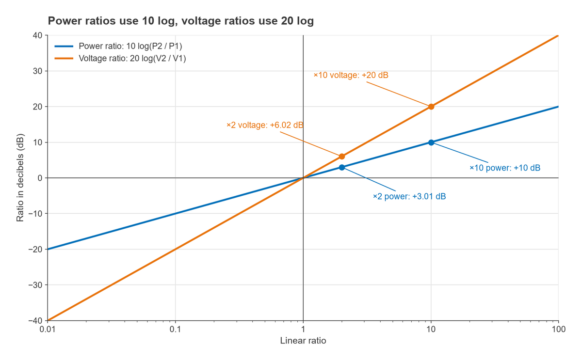
Power in a resistance is proportional to the square of voltage, P = V2/R. When two voltages are measured across the same impedance, the power ratio in decibels becomes
10 log10(V22 / V12) = 20 log10(V2 / V1)
So a factor of two in voltage is 6.02 dB, and a factor of ten is 20 dB. The 20 log form gives the same decibel value as the 10 log power form only when both voltages sit across equal impedances. Comparing 1 V across 50 Ω with 1 V across 75 Ω gives 0 dB in voltage terms but a power ratio of 10 log10(75/50) = 1.76 dB. Reflection coefficients and S-parameters are voltage-wave ratios, which is why return loss uses −20 log10|Γ|; see S-parameters explained.
dBµV in a 50 Ω system
EMC receivers and many test sets report levels in dBµV, decibels relative to 1 µV. In 50 Ω, 0 dBm corresponds to √(0.001 × 50) = 0.2236 V rms, which is 20 log10(223,607) = 106.99 dBµV. The conversion is therefore
dBµV = dBm + 107 (in 50 Ω)
In a 75 Ω system, used for cable television, the constant becomes about 108.75. A receiver input specified as −100 dBm in 50 Ω therefore needs 7 dBµV, or 2.24 µV rms.
Worked Example: Cascading Gains and Losses in dB
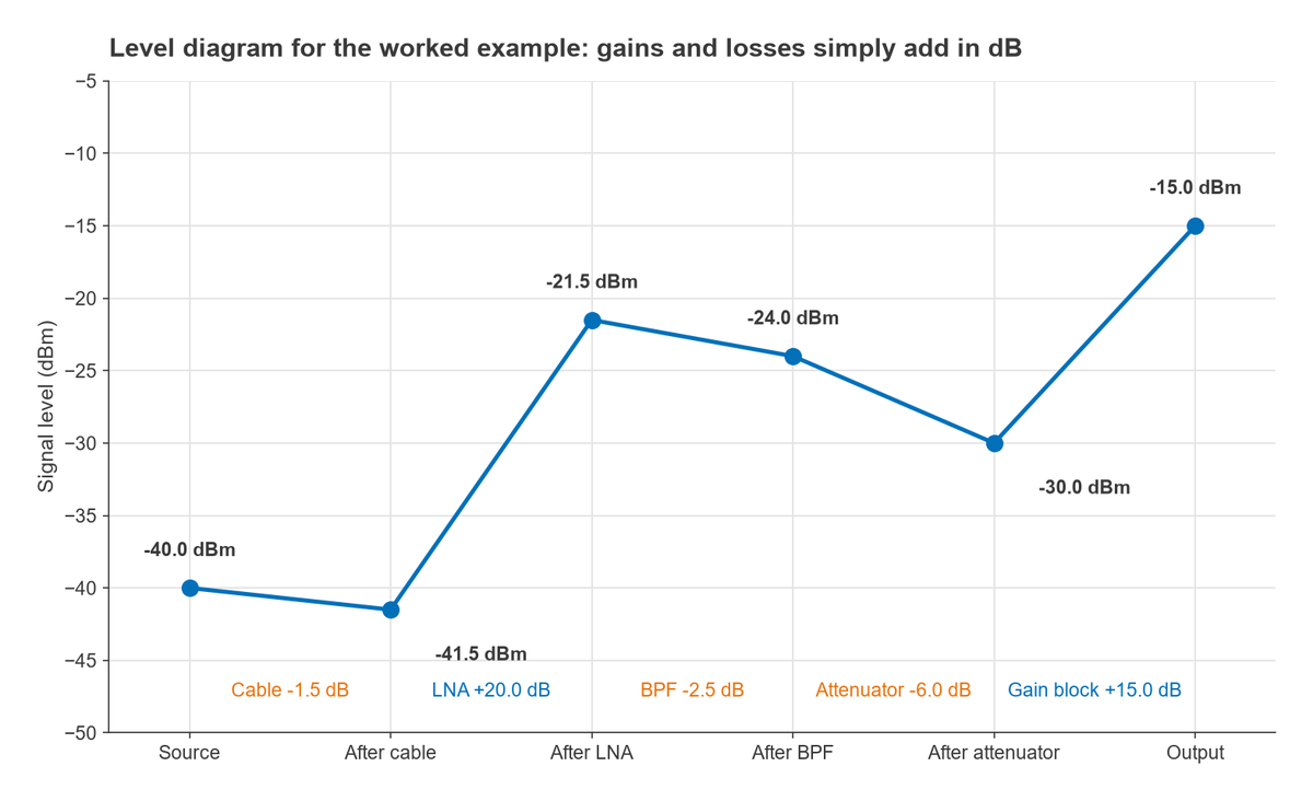
A −40 dBm signal from an antenna passes through a cable with 1.5 dB of loss, an LNA with 20 dB of gain, a band-pass filter with 2.5 dB of insertion loss, a 6 dB attenuator and a gain block with 15 dB of gain. In decibels the levels are found by addition:
- After the cable: −40 − 1.5 = −41.5 dBm.
- After the LNA: −41.5 + 20 = −21.5 dBm.
- After the filter: −21.5 − 2.5 = −24.0 dBm.
- After the attenuator: −24.0 − 6 = −30.0 dBm.
- At the output: −30.0 + 15 = −15.0 dBm.
The net gain is 25 dB. The same calculation in linear units is 0.1 µW × 0.708 × 100 × 0.562 × 0.251 × 31.6 = 31.6 µW, and 10 log10(0.0316) = −15.0 dBm, so the two methods agree. The decibel version needs no calculator, which is why link budgets such as Part 15 of the series, link budgets, are tabulated this way.
When decibels do not simply add
Gains and losses add in dB because they multiply in linear terms. Powers from independent sources add in linear terms, so their dBm values cannot be summed directly. Two uncorrelated 0 dBm signals combine to 2 mW, or +3.01 dBm, not 0 dBm. Noise from several stages is combined the same way, which is the basis of the cascaded noise figure calculation. The rule: convert to milliwatts, add, and convert back.
Frequently Asked Questions
What is dBm?
dBm is power expressed in decibels relative to 1 mW. 0 dBm is 1 mW, +10 dBm is 10 mW, +30 dBm is 1 W and −30 dBm is 1 µW. It is an absolute level, unlike dB, which is only a ratio.
How do you convert dBm to watts?
Use P(W) = 10(dBm − 30)/10, or P(mW) = 10dBm/10. For example, +37 dBm is 100.7 = 5.01 W. To go the other way, dBm = 10 log10(P in mW).
What is the difference between dB and dBm?
dB is a ratio between two powers, such as a gain or a loss. dBm is an absolute power referenced to 1 mW. Adding a gain in dB to a level in dBm gives a new level in dBm; adding two levels in dBm has no meaning.
What is dBc?
dBc is a level relative to the carrier. A harmonic at −45 dBc is 45 dB below the carrier power at the same point. Spurious emissions, harmonics and phase noise (dBc/Hz) are commonly specified this way.
Why do RF engineers use decibels?
Radio signals span more than 15 orders of magnitude, and a signal chain multiplies many gains and losses together. Decibels compress the range into manageable numbers and turn multiplication into addition, so a whole receiver lineup or link budget can be checked by hand.
Related Topics
Other pages in this section cover frequency and wavelength, RF frequency bands and electromagnetic waves. For definitions of other units and terms, see the RF and wireless glossary.