

An RF oscillator is an amplifier whose output is fed back to its input through a frequency-selective network, so that it sustains a periodic signal with no input applied. It oscillates at the one frequency where the loop gain is exactly one and the loop phase shift is a multiple of 360°, the Barkhausen criteria. Every transmitter, receiver and clocked converter depends on one.
Frequency generation in a radio is rarely a single oscillator. A stable crystal reference sets the accuracy, a voltage-controlled oscillator (VCO) supplies the RF signal, and a phase-locked loop (PLL) or direct digital synthesizer ties them together so the output can be tuned in precise steps. This hub explains the principle all of these share and links to the pages on each block, within the wider RF design reference.
How RF Oscillators Work
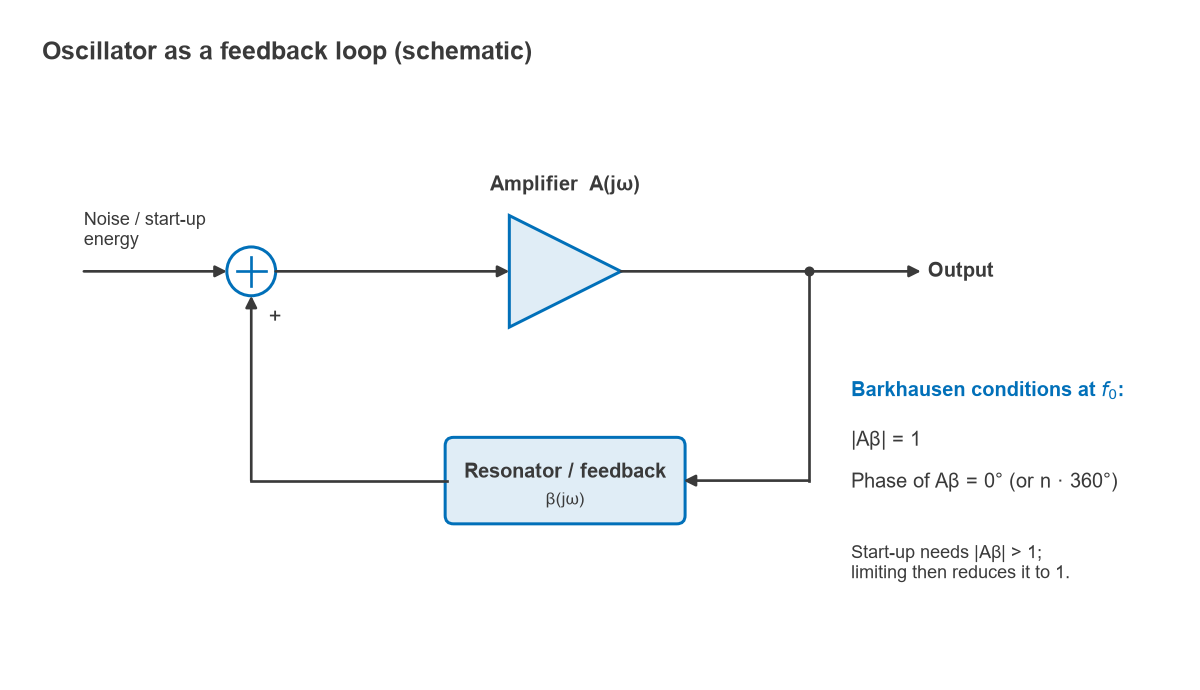
Model the oscillator as an amplifier with gain A(jω) and a feedback network with transfer function β(jω), connected in a loop. With an external input x the closed-loop response is
y / x = A / (1 − Aβ)
When the loop gain Aβ equals exactly 1, the denominator is zero and the circuit produces a finite output with no input at all. Written as two conditions at the oscillation frequency f0, these are the Barkhausen criteria:
- Magnitude: |A(jω0)β(jω0)| = 1
- Phase: ∠A(jω0)β(jω0) = 0° or an integer multiple of 360°
The phase condition sets the frequency. A resonator in the feedback path, such as an LC tank, a crystal, a ceramic resonator or a transmission-line section, changes phase rapidly near its resonance, so the zero-phase condition is met at only one frequency close to that resonance. For an LC tank with L = 10 nH and C = 1 pF, f0 = 1 / (2π√(LC)) = 1.59 GHz.
Start-up and amplitude limiting
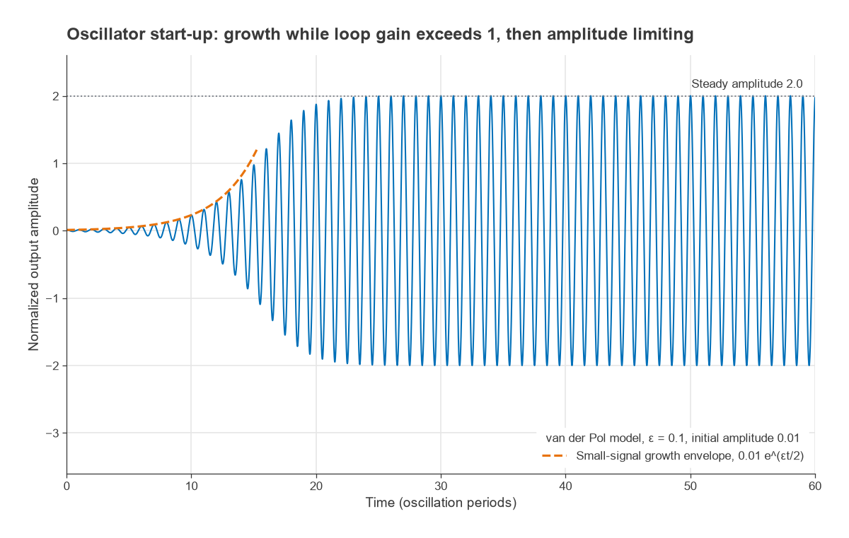
A loop gain of exactly one cannot be designed or held over temperature and component tolerance. Practical oscillators are therefore designed with a small-signal loop gain greater than one, commonly by a factor of two to three. Thermal noise and the switch-on transient contain energy at f0; with loop gain above one, each pass round the loop makes that component larger, and the amplitude grows exponentially. As it grows, the active device begins to compress or its bias shifts, and the large-signal gain falls until the average loop gain settles at exactly one. The steady amplitude is set by that nonlinearity or by a separate automatic level control.
The Barkhausen criteria are necessary but not sufficient. A circuit can satisfy them and still fail to start if the gain margin is too small at turn-on, or can oscillate at an unwanted frequency where a parasitic path also meets the phase condition. Designers check the loop with small-signal analysis for start-up, then with large-signal or harmonic balance simulation for steady-state amplitude and harmonics. The one-port view, in which the active device presents a negative resistance that cancels the resonator’s loss, is equivalent and is the usual approach for microwave oscillators.
What Makes a Good Oscillator
Four properties dominate oscillator specifications:
- Frequency accuracy and stability: initial tolerance, drift with temperature, supply and ageing, quoted in ppm. At 2.4 GHz, a 2 ppm error is 4.8 kHz and a 20 ppm error is 48 kHz.
- Phase noise: the random variation of phase that spreads the carrier into a skirt, quoted in dBc/Hz at an offset. It is governed largely by the loaded Q of the resonator; Leeson’s model shows close-in noise falling as the square of loaded Q.
- Tuning range and tuning sensitivity: for a VCO, the frequency span and the slope KVCO in MHz per volt.
- Output power, harmonics and pushing and pulling: sensitivity of frequency to supply voltage and to load impedance changes.
These goals conflict. A high-Q quartz crystal gives excellent stability and phase noise but can be pulled only a few tens of ppm. An LC VCO tunes over tens of percent but drifts and is noisier. Frequency synthesis resolves the conflict by locking a tunable oscillator to a stable reference. In an integer-N PLL, fout = N · fref; a 10 MHz reference and N = 240 give 2.4 GHz. Inside the loop bandwidth, the reference phase noise is multiplied by 20log10(N), here 47.6 dB, which is one reason PLL designers care so much about the reference.
Resonator Q is treated in its own right on the Q factor page, and phase noise measurement is covered in phase noise measurement.
Topics in This Section
- PLLs, Frequency Synthesis and Phase Noise (Radio Architectures Pt 10): how a PLL locks a VCO to a reference, integer-N and fractional-N synthesis, and the phase noise of the result.
- VCO Design: Colpitts, Clapp and Cross-Coupled: common topologies, varactor tuning and the start-up condition for each.
- Crystal Oscillators: XO, TCXO, OCXO Compared: reference oscillators and how temperature compensation and ovens improve stability.
- Direct Digital Synthesis (DDS): generating a waveform from a phase accumulator and DAC, with fine resolution and fast switching.
- PLL Loop Filter Design: choosing loop bandwidth and phase margin, and calculating component values.
The oscillator’s output usually drives a mixer, so this section connects directly to mixers and frequency conversion. Clock quality also limits data converters, as discussed in DACs and the transmit chain.
Frequently asked questions
How do RF oscillators work?
An amplifier feeds part of its output back to its input through a resonator. At the frequency where the loop phase is a multiple of 360° and the loop gain exceeds one, noise is amplified on every pass until the device compresses and the loop gain settles at one. The result is a steady sine wave near the resonator frequency.
What are the Barkhausen criteria?
They are the conditions for sustained oscillation in a feedback loop: the magnitude of the loop gain Aβ must equal one, and its phase must be zero or a multiple of 360°. They are necessary conditions, so a circuit that meets them still needs extra start-up gain and a check for unwanted oscillation modes.
Why is resonator Q so important?
A high-Q resonator changes phase quickly with frequency, so small phase disturbances in the amplifier move the frequency only slightly. That gives better stability and lower phase noise. It is why crystal and dielectric resonators outperform on-chip LC tanks in both respects.
Related topics
Oscillator design draws on RF fundamentals, S-parameters for negative-resistance analysis, and transmission line theory for resonators at microwave frequencies. Its effect on a complete radio is covered in phase noise and in the Radio Architectures series. Terms are defined in the wireless terms glossary.