

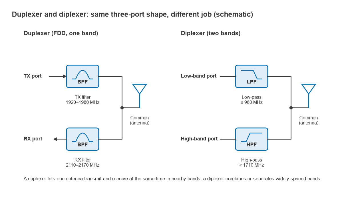
A duplexer and a diplexer are both three-port filter networks that connect two signal paths to one common port, but they separate different things. A duplexer separates the transmit and receive frequencies of one radio so it can transmit and receive through one antenna at the same time. A diplexer separates two different frequency bands, such as a low band and a high band, onto separate ports.
Both belong to the family of multiplexing filters described in the RF filters section of the RF design guide. This page compares their function, the isolation and loss specifications that matter for each, the main technologies (cavity, ceramic and acoustic), and the larger multiplexers used in modern front ends.
Function: what each one separates
Duplexer
A duplexer serves frequency-division duplex (FDD) systems, where the transmitter and receiver operate simultaneously on two frequencies separated by a fixed duplex gap. A familiar example is the 2 GHz cellular band with uplink at 1920 to 1980 MHz and downlink at 2110 to 2170 MHz. The duplexer contains two bandpass filters joined at the antenna port: the TX filter passes the uplink band and rejects the downlink band, and the RX filter does the opposite.
The difficulty is that the two bands are close together and the power levels are wildly different. The transmitter may deliver +24 dBm or more to the antenna while the receiver is trying to detect signals near −100 dBm. The duplexer must keep the transmit signal and its noise out of the receiver across a gap of only 130 MHz in this example, about 6% of the centre frequency.
The word “duplexer” is also used more loosely for any device that lets a transmitter and receiver share an antenna, including a transmit/receive switch in a time-division system and a circulator in radar. Those devices separate signals by time or direction rather than frequency. This page uses the frequency-selective meaning.
Diplexer
A diplexer splits or combines two bands that are widely separated, often by an octave or more. A typical pairing is a low-pass filter and a high-pass filter sharing a junction, so one port carries, for example, 700 to 960 MHz and the other 1710 to 2690 MHz. Diplexers appear in multiband antennas, in cable systems that separate upstream and downstream traffic, in satellite receivers that combine terrestrial and satellite feeds on one coax, and in test setups.
Because the bands are far apart, diplexer filters are usually simpler and lower in loss than duplexer filters. The power ratio between the paths is also often much smaller, so isolation requirements are more modest.
Duplexer vs diplexer comparison
The ranges below are approximate and typical as of 2026. They vary with band, size and technology, and a specific design should rely on the part’s datasheet.
| Attribute | Duplexer | Diplexer |
|---|---|---|
| Separates | TX and RX of one FDD band | Two different bands |
| Band spacing | Small duplex gap, a few percent | Wide, often an octave or more |
| Filter type | Two bandpass filters | Low-pass + high-pass, or two bandpass |
| Isolation between ports | High: roughly 50 to 60 dB for handset parts, often higher for base-station cavity units | Moderate: often 20 to 50 dB |
| Insertion loss | About 1 to 2.5 dB for acoustic parts; a few tenths of a dB for cavities | Often well under 1 dB |
| Power handling | Must carry full TX power on the TX side | Depends on application |
| Typical technology | SAW, BAW, ceramic, cavity | LC, LTCC, microstrip, cavity |
Isolation specifications
A duplexer’s datasheet normally gives two isolation figures, and they protect against different problems.
- TX-to-RX isolation in the TX band. This limits how much of the transmit carrier reaches the LNA. It is provided mostly by the RX filter’s rejection at the TX frequency. Too little causes LNA compression and, through intermodulation with other signals, receiver desensitisation.
- TX-to-RX isolation in the RX band. This limits how much transmitter noise falling in the receive band reaches the LNA. It is provided mostly by the TX filter’s rejection at the RX frequency. Once that noise is in the RX band, no later filter can remove it.
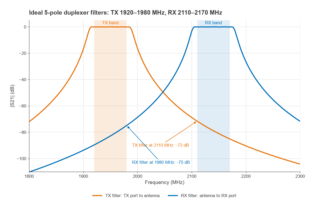
The ideal 5-pole Chebyshev filters in Figure 2 reject the opposite band edge by 72 dB (TX filter at 2110 MHz) and 75 dB (RX filter at 1980 MHz). Real duplexers fall short of such ideal numbers, because energy leaks through the common junction, through package and board coupling and through the ground. That is why practical isolation specifications sit lower than the filter prototype alone would suggest, and why layout around a duplexer matters.
Worked example: how much RX-band isolation is needed
Assume a receiver with a 3 dB noise figure, so its input-referred noise density is −174 + 3 = −171 dBm/Hz. Assume the PA output noise in the receive band is −135 dBm/Hz at the duplexer’s TX port (an illustrative value; it depends on the PA and the transmit chain).
- To keep leaked noise 10 dB below the receiver’s own noise, it must reach the LNA at no more than −181 dBm/Hz.
- The required RX-band isolation is −135 − (−181) = 46 dB.
- With the leaked noise exactly 10 dB below the receiver noise, the sensitivity loss is 10log(1 + 0.1) = 0.41 dB.
On the TX-band side, a PA delivering +26 dBm to the duplexer’s TX port with 50 dB of TX-band isolation puts −24 dBm of carrier at the LNA input. The LNA and the mixer that follows must handle that level without compressing or generating intermodulation products that land in the receive channel. Both figures feed the receiver sensitivity budget.
Diplexer isolation and crossover
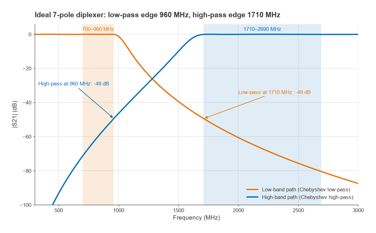
For a diplexer, the main specifications are insertion loss in each passband, rejection of the other band and return loss at the common port. In the ideal 7-pole Chebyshev diplexer of Figure 3, with a 960 MHz low-pass edge and a 1710 MHz high-pass edge, each path rejects the other band’s edge by 49 dB. The two filters must also be designed together. Each filter loads the other at the junction, and the reactance of the “off” filter in the “on” filter’s band has to be absorbed into the design, which is usually done by optimisation in a circuit simulator.
Cavity vs acoustic filters
The technology choice follows from bandwidth, loss, power and size. The governing relationship is the midband insertion loss of a bandpass filter with resonators of unloaded Qu:
IL ≈ 4.343 × Σgk / (FBW × Qu) dB
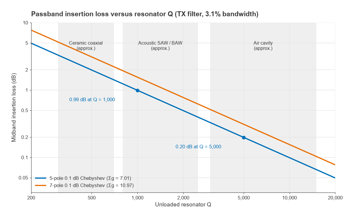
where gk are the lowpass prototype element values and FBW is the fractional bandwidth. For a 5-pole 0.1 dB ripple Chebyshev, Σg = 1.1468 + 1.3712 + 1.9750 + 1.3712 + 1.1468 = 7.011. The TX filter above has FBW = 60/1950 = 3.08%. With Qu = 1000, IL ≈ 4.343 × 7.011 / (0.0308 × 1000) = 0.99 dB. With Qu = 5000, it is 0.20 dB. More poles give steeper skirts but more loss, which is the central trade-off in duplexer design. Resonator Q itself is covered in Q factor.
- Air cavity and coaxial cavity duplexers use metal resonators with unloaded Q in the thousands. They have low loss, handle tens to hundreds of watts and are stable with temperature, which suits base stations and repeaters. They are large and heavy.
- Ceramic coaxial (dielectric) filters shrink the resonators using high-permittivity ceramic. Q is lower, typically in the hundreds, and size sits between cavity and acoustic parts.
- Acoustic filters (SAW and BAW) convert the signal into acoustic waves in a piezoelectric material. The wavelength is about five orders of magnitude shorter than the electromagnetic wavelength, so the resonators are tiny and fit in millimetre-sized packages. Q is typically around a thousand or more at low gigahertz frequencies, power handling is limited to handset levels, and temperature drift needs compensation. The trade-offs between the two acoustic types are covered in SAW vs BAW filters.
Diplexers with widely spaced bands rarely need such high Q, so they are commonly built as LC filters, in LTCC, or as microstrip filters at higher frequencies.
Triplexers, quadplexers and multiplexers
Extending the idea, a multiplexer joins three or more filters at a common port. A triplexer may split three bands, and a quadplexer combines two duplexers so that two FDD bands can operate at once, as needed for carrier aggregation. Each added filter loads the junction, so the matching network at the common port becomes harder and loss tends to rise. Modern handset front ends integrate these multiplexers with switches, LNAs and PAs in a single front-end module, and band switching is handled by RF switches between the multiplexers and the antenna.
Frequently asked questions
What is the difference between a duplexer and a diplexer?
A duplexer separates the transmit and receive frequencies of one FDD band so a radio can transmit and receive simultaneously through one antenna. A diplexer separates two different, usually widely spaced, frequency bands onto two ports. Both are three-port frequency-selective networks, but the duplexer faces a much harder isolation problem.
Can a diplexer be used as a duplexer?
Only if its filters are designed for the TX and RX frequencies of the band with enough isolation. A general-purpose low-pass/high-pass diplexer has far too gentle a transition for a duplex gap of a few percent, so it cannot protect a receiver from its own transmitter.
Why are cavity duplexers used in base stations?
Base stations transmit tens of watts or more and need very low loss and high isolation. Cavity resonators offer unloaded Q in the thousands and high power handling, which acoustic filters cannot match. Size and weight matter less on a mast than in a phone.
Related topics
The specifications used to describe these filters are defined in RF filter specifications, and a full cellular front end is described in 5G RF front end design. Terms used here are defined in the wireless terms glossary.