

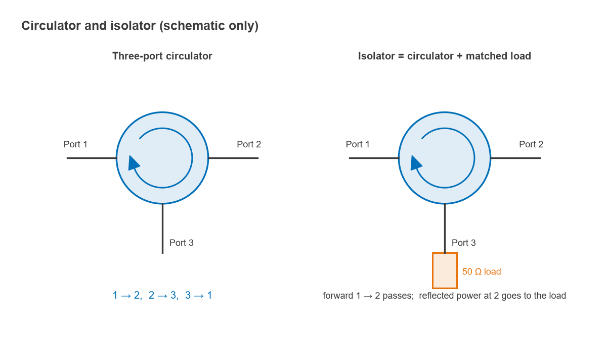
Circulators and isolators are ferrite non-reciprocal devices: a magnetised ferrite makes them pass signals in one rotational direction and not the other. A circulator has three ports and routes power from port 1 to 2, 2 to 3 and 3 to 1. An isolator is a circulator with its third port terminated in a matched load, so it passes power forward and absorbs anything reflected back.
These are among the few passive components that break reciprocity, the rule that S21 = S12 for any network made of ordinary conductors and dielectrics. That property makes them the standard way to protect power amplifiers from load mismatch and to share one antenna between a transmitter and a receiver. This page explains the ferrite physics, the S-parameter description, the specifications that matter and two worked examples. It belongs to the passive components section of the RF design map.
How a Circulator Routes Signals
An ideal, matched, lossless three-port circulator with clockwise rotation has the S-parameter matrix
S = [ 0 0 1 ; 1 0 0 ; 0 1 0 ]
read row by row: S21 = S32 = S13 = 1 and every other term is zero. Power entering port 1 leaves at port 2, power entering port 2 leaves at port 3, and power entering port 3 leaves at port 1. The matrix is not symmetric, which is the definition of non-reciprocity. Reversing the bias magnet reverses the direction of rotation.
A useful consequence is that any lossless, matched three-port must be a circulator; a matched, lossless, reciprocal three-port is impossible, which is why Wilkinson dividers need a resistor. Real circulators have small reflections, some loss and finite isolation, so S11, S31 and similar terms are small but not zero.
An isolator is formed by terminating port 3 in a matched load. Forward power from port 1 reaches port 2. Power reflected from whatever is connected to port 2 travels to port 3 and is absorbed. Some isolators are built from a circulator in this way; others, particularly in waveguide, use resonance absorption or field displacement in a ferrite slab, without a separate load.
Ferrite Operation
Ferrites such as yttrium iron garnet (YIG) and various nickel and lithium ferrites are ceramic magnetic insulators. Their electron spins carry magnetic moments, and a static bias field H0 aligns them. A spin disturbed from alignment precesses around H0 at the Larmor frequency
f0 = γ H0, with γ ≈ 2.8 MHz/Oe (28 GHz/T)
An RF magnetic field that rotates in the same direction as the precession couples to it strongly; one rotating the other way couples only weakly. The material is therefore described by Polder’s tensor permeability, and for circularly polarised fields it has two different scalar permeabilities:
μ± = 1 + ωm / (ω0 ∓ ω), where ω0 = 2πγH0 and ωm = 2πγ(4πMs)
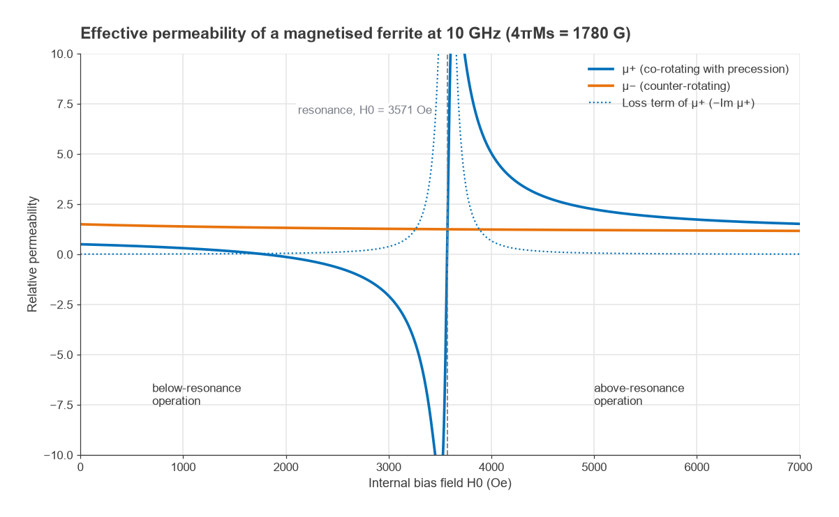
Here 4πMs is the saturation magnetisation, about 1,780 G for YIG, giving fm = 4.98 GHz. At 10 GHz, resonance occurs at an internal field of 1010/2.8 × 106 = 3,571 Oe, ignoring demagnetisation. Well above resonance, at H0 = 6,000 Oe, μ+ = 1.73 and μ− = 1.19. The two rotation senses see different propagation constants, so waves travelling one way through the ferrite acquire a different phase from waves travelling the other way.
The Junction Circulator
The most common construction is the Y-junction circulator: a ferrite disc, or a pair of discs, sandwiched between conductors at the junction of three lines spaced 120° apart, with a permanent magnet providing H0. Without bias, the disc supports a standing-wave resonance that couples equally to the two output ports. With bias, the different μ+ and μ− split this into two counter-rotating modes at slightly different frequencies. Driving between them rotates the standing-wave pattern by 30°, which places a null at one port and a maximum at the other. The disc dimensions set the operating frequency and the splitting sets the bandwidth.
Designs operate either below resonance, with a low bias field, or above resonance, with a field larger than the resonant value. Both avoid the loss peak at resonance shown in Figure 2. Below-resonance designs are compact and common at microwave frequencies; above-resonance designs are often used at lower frequencies, where a below-resonance design would need a field too small to keep the ferrite saturated. Junction circulators are made in coaxial, stripline, microstrip and waveguide forms, and drop-in and surface-mount versions sit directly on a PCB.
Key Specifications
- Insertion loss: forward loss, S21. A few tenths of a dB is typical for a single junction over its rated band. At high power this loss turns into heat in the ferrite: 0.4 dB at 10 W is roughly 0.9 W dissipated.
- Isolation: reverse transmission, for example S12 for an isolator. Around 20 dB is a typical single-junction figure, with more near band centre and less at the edges. A dual-junction device in one housing gives roughly double the isolation in dB, at the cost of roughly double the loss.
- VSWR or return loss at each port, usually specified with the other ports terminated in matched loads. See VSWR and return loss.
- Bandwidth: the range over which the loss, isolation and VSWR limits are all met. Octave bandwidths are achievable; narrower bands give better performance.
- Power handling: forward power, plus reflected power for an isolator. The internal termination must absorb whatever the load reflects, up to the full forward power into an open or short circuit.
- Temperature range: ferrite magnetisation falls with temperature, shifting the operating band. Temperature-compensated designs and the specified operating range matter in outdoor equipment.
- Intermodulation: ferrites are mildly nonlinear and can generate passive intermodulation, which matters in base stations where transmit products fall in the receive band.
The isolation of an isolator also depends on its termination. Reverse power from port 2 reaches port 3, part of it reflects from an imperfect load, and that part continues to port 1. A termination with 20 dB return loss therefore limits the device to roughly 20 dB isolation, whatever the junction itself achieves.
Worked Example: Protecting a Power Amplifier
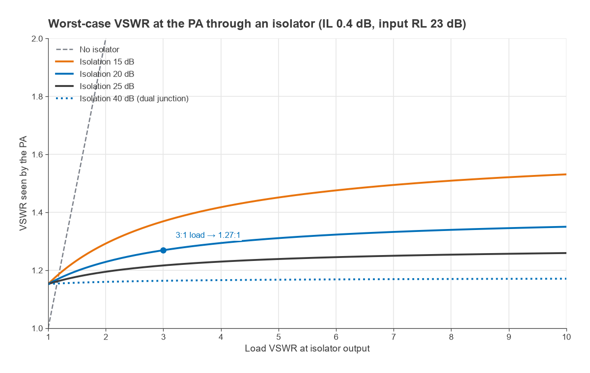
A power amplifier designed for a 50 Ω load delivers 10 W through an isolator with 0.4 dB insertion loss, 23 dB input return loss and 20 dB isolation. The antenna or load presents a 3:1 VSWR, so |ΓL| = (3 − 1)/(3 + 1) = 0.5.
- Linear terms: |S21| = 10−0.4/20 = 0.955, |S11| = 10−23/20 = 0.071, |S12| = 0.1.
- Reflection seen by the PA: Γin ≈ S11 + S21S12ΓL. In the worst case the terms add in phase: 0.071 + 0.955 × 0.1 × 0.5 = 0.119, a VSWR of 1.27:1. In the best case they subtract to 0.023, or 1.05:1.
- Power at the isolator output: 10 × 0.9552 = 9.12 W. A quarter of it, 2.28 W, is reflected, and about 2.08 W reaches the internal load after the second pass through the junction.
Without the isolator the PA would see the full 3:1 mismatch, which can shift its operating point on the load-pull contours, reduce output power, raise distortion or overstress the device. With it, the PA sees a load close to 50 Ω regardless of the antenna. The cost is 0.4 dB of output power, 0.9 W of heat in the ferrite, and the need to rate the load for reflected power. Isolators are also placed after oscillators and between cascaded amplifier stages to prevent load pulling and interaction between stages.
Circulators as Duplexers
Connecting a transmitter to port 1, the antenna to port 2 and a receiver to port 3 lets one antenna serve both, which is standard practice in radar and in transmit/receive modules of phased arrays. Unlike a filter duplexer, a circulator separates signals by direction, not frequency, so transmit and receive can share the same frequency. That is also its limitation: the transmitter-to-receiver coupling is set by the circulator isolation plus the antenna reflection.
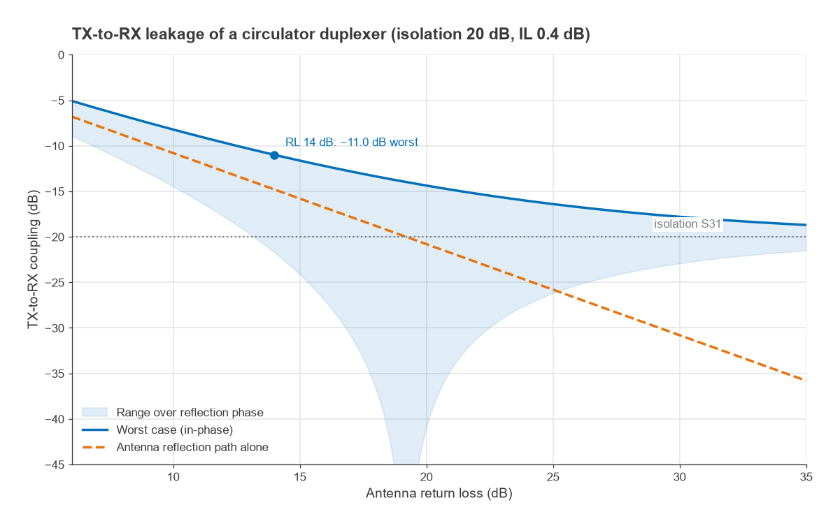
Transmit power reaches the receiver by two paths: directly through the finite isolation S31, and by travelling to the antenna, reflecting with ΓA and continuing from port 2 to port 3. With 20 dB isolation, 0.4 dB loss per pass and an antenna return loss of 14 dB (|ΓA| = 0.2), the reflected path is 0.2 × 0.9552 = 0.182, or −14.8 dB. Combined with the direct path of 0.1, the total coupling lies between −21.7 dB and −11.0 dB depending on phase. A +30 dBm transmitter could therefore put as much as +19 dBm into the receiver.
The antenna match, not the circulator, sets the limit once the return loss falls below the isolation value. Practical systems therefore add protection: a pulsed radar uses a limiter and only receives between pulses, while full-duplex radios add analog and digital self-interference cancellation after the circulator. In front-end modules for cellular FDD bands, filter duplexers remain the normal choice because they provide much higher isolation between separated bands.
Practical Considerations
- Magnetic fields: the bias magnet can be disturbed by nearby steel or other magnets, and it can affect nearby magnetic components. Mounting guidance in the data sheet should be followed.
- Size: ferrite devices scale with wavelength. Below a few hundred megahertz they become large, and lumped-element designs are used to shrink them.
- Non-ferrite alternatives: active circulators built from amplifiers, and time-modulated circuits using switched or varactor-modulated networks, can provide non-reciprocity on chip. They trade noise, linearity or power handling for integration.
- Measurement: a three-port device is measured on a two-port VNA by terminating the unused port in a good load, then repeating for each port pair. Load quality limits the measurable isolation.
Frequently Asked Questions
What is the difference between a circulator and an isolator?
A circulator has three ports and routes power in rotation, 1 to 2, 2 to 3 and 3 to 1. An isolator is a two-port device, usually a circulator with port 3 terminated in a matched load, so it passes power forward and absorbs reflections. Circulators share an antenna between TX and RX; isolators protect sources from mismatch.
How does a ferrite circulator work?
A bias magnet makes the ferrite’s electron spins precess, so RF fields rotating with the precession see a different permeability from fields rotating against it. In a junction circulator this splits the disc resonance into two modes and rotates the field pattern so that power reaches only the next port in sequence.
What isolation does a circulator typically have?
A single-junction device typically gives around 20 dB across its band, with more near the centre frequency. Dual-junction devices give roughly twice that in dB. In use, the effective isolation is often limited by the match of the load or antenna on the adjacent port.
Why is an isolator used after a power amplifier?
It keeps the impedance seen by the amplifier close to 50 Ω whatever the antenna does. Reflected power goes into the isolator’s load instead of back into the transistor, which protects the device and keeps its gain, output power and linearity stable.
Related Topics
Other passive building blocks are covered in directional couplers, hybrid couplers and Wilkinson power dividers. For the network theory, see S-parameters and VSWR and return loss. The passive components hub lists every topic in this section, and radar basics shows a circulator in a complete system.