

A balun is a passive three-port network that converts between an unbalanced signal, referenced to ground, and a balanced signal carried as two equal and opposite voltages or currents. It often transforms impedance at the same time. Baluns connect single-ended coaxial and microstrip circuits to differential devices such as dipole antennas, double-balanced mixers, differential amplifiers and ADC inputs.
The name is a contraction of “balanced to unbalanced”. Three families cover most RF work: magnetic transformers, coupled-line structures such as the Marchand balun, and lumped LC networks. Each trades bandwidth, size, loss and balance differently. This page explains how each type works, how balance is specified, and how to design a lumped LC balun, with a worked 2.45 GHz example. It belongs to the transmission lines and impedance matching section of the RF design reference.
Balanced and unbalanced signals
A coaxial cable or a microstrip line is unbalanced: one conductor carries the signal and the other is ground. A twin-lead line, a dipole or a differential IC pin pair is balanced: both conductors have the same impedance to ground and carry signals of equal magnitude and opposite phase. Any pair of node voltages V+ and V− can be split into a differential mode, Vd = V+ − V−, and a common mode, Vc = (V+ + V−)/2. An ideal balun delivers only differential mode at its balanced port and rejects common mode completely.
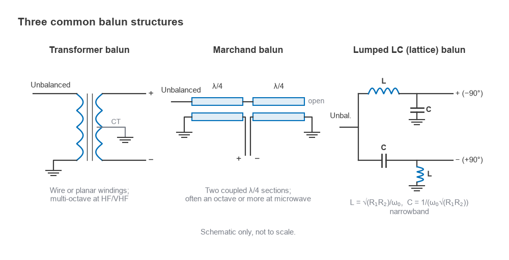
Connecting a coaxial line straight to a dipole shows why the balun is needed. The inner conductor drives one arm of the dipole, but the current on the inside of the shield divides between the other arm and the outside surface of the shield. The shield then radiates, distorts the antenna pattern and couples the antenna to whatever the cable passes near. The same imbalance in a mixer or ADC front end lets common-mode noise and even-order distortion through. The mode description is formalised in mixed-mode S-parameters.
Current and voltage baluns
A voltage balun forces the two balanced terminals to equal and opposite voltages with respect to ground. A centre-tapped transformer with its tap grounded does this. If the balanced load is itself not perfectly symmetrical, the currents in the two terminals will differ, and the difference returns through ground.
A current balun forces equal and opposite currents in the two terminals, whatever their voltages to ground. The classic form is a transmission line, coaxial or bifilar, wound on a ferrite core or threaded through ferrite beads. Differential current flows inside the line and sees only its characteristic impedance. Common-mode current flows on the outside and sees the high inductive and resistive impedance of the winding on the core, so it is suppressed. This is also called a choke balun or Guanella balun. For antenna feeds, the current balun is usually preferred because the quantity that matters is antenna current balance, and an asymmetric antenna or feed environment upsets a voltage balun. A common rule of thumb is that the common-mode impedance should be several times, often ten times, the load impedance across the band.
Transformer baluns
A magnetic transformer with an isolated secondary is the most direct balun. The primary is driven single-ended and the secondary floats, so its two ends carry equal and opposite voltages. The turns ratio n sets the impedance ratio:
Zbalanced = n2 · Zunbalanced
A 1:2 turns ratio therefore converts 50 Ω unbalanced to 200 Ω balanced, the familiar 1:4 balun. A grounded centre tap on the secondary gives a voltage balun and a convenient DC feed point for a differential amplifier. Wire-wound transformers on ferrite cores cover several octaves at HF and VHF. The low-frequency limit is set by the magnetizing inductance, which must have a reactance well above the source impedance. The high-frequency limit is set by leakage inductance and interwinding capacitance, which disturb both the match and the balance. Transmission-line transformers, in which the windings form a line of defined characteristic impedance, absorb those parasitics into the line and extend the upper frequency. Printed and on-chip spiral transformers apply the same idea at microwave frequencies, with coupling coefficients typically well below that of a ferrite-core part.
The Marchand balun
The Marchand balun is the standard planar balun at microwave frequencies. It consists of two coupled-line sections, each a quarter wavelength long at the centre frequency. The unbalanced input drives one line through both sections and ends in an open circuit. The coupled lines are grounded at their far ends, and their inner ends form the balanced port. At the centre frequency, the open-circuited quarter-wave stub appears as a short at the junction, and the two coupled sections deliver currents of equal magnitude and opposite direction to the balanced port.
Because it is built from distributed quarter-wave sections rather than lumped resonators, a Marchand balun often reaches an octave or more of bandwidth with good balance, depending on how tightly the lines are coupled. Tighter coupling, as obtained with broadside or multi-layer structures, gives wider bandwidth. The balanced-port impedance is set by the even- and odd-mode impedances of the coupled lines, described on the transmission line parameters page. The cost is size at low frequencies. On a substrate with an effective permittivity of 3.3, a quarter wavelength at 2.45 GHz is
λ/4 = c / (4f√εeff) = 3×10⁸ / (4 × 2.45×109 × 1.817) ≈ 16.8 mm
so a straight Marchand balun is about 34 mm long. Meandering, higher-permittivity substrates or lumped-element equivalents reduce that. The underlying quarter-wave behaviour is the same as in the quarter-wave transformer.
Lumped LC balun design
When board area is tight and the band is narrow, a lumped LC balun is often the smallest solution. The lattice form uses two arms fed from the unbalanced port. One arm is a low-pass section, a series inductor followed by a shunt capacitor, which delays the signal by 90°. The other is a high-pass section, a series capacitor followed by a shunt inductor, which advances it by 90°. The two outputs are therefore 180° apart.
Each arm behaves as a lumped quarter-wave transformer with characteristic impedance Zm. To match an unbalanced resistance R1 to a balanced resistance R2, each arm sees half the balanced load, R2/2, and transforms it to Zm2/(R2/2). The two arms appear in parallel at the input, so the input resistance is Zm2/R2. Setting that equal to R1 gives
Zm = √(R1R2), L = Zm/ω0, C = 1/(ω0Zm)
Worked example: 50 Ω to 100 Ω at 2.45 GHz
- Zm = √(50 × 100) = 70.71 Ω.
- ω0 = 2π × 2.45×109 = 1.539×10¹⁰ rad/s.
- L = 70.71 / 1.539×1010 = 4.59 nH.
- C = 1 / (1.539×1010 × 70.71) = 0.919 pF.
- Each arm uses one 4.59 nH inductor and one 0.919 pF capacitor, in opposite positions. In practice these round to the nearest available values, and the pad and part parasitics described in RF component parasitics are absorbed by simulation and tuning.
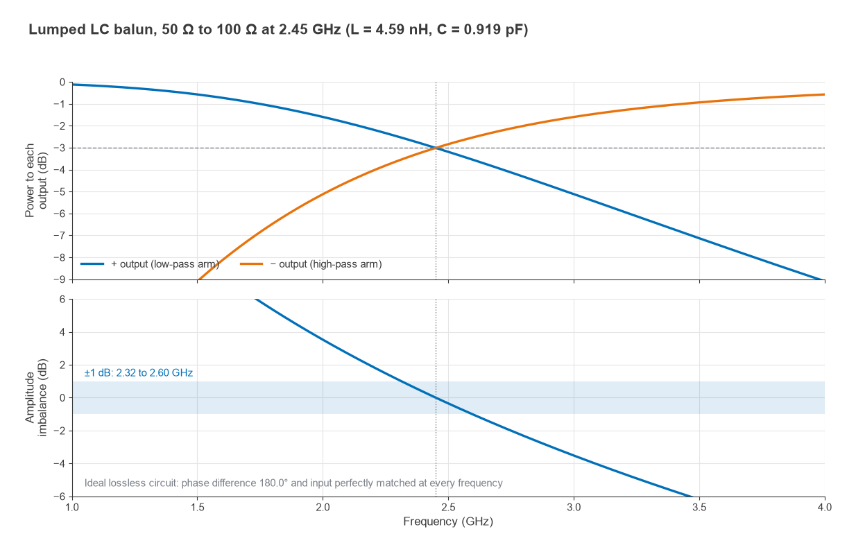
A circuit analysis of the ideal network, with the balanced load represented as two 50 Ω halves to ground, gives the response in Figure 2. The ideal lattice balun is perfectly matched at its input at all frequencies, and the two outputs stay exactly 180° apart, because the low-pass and high-pass arms are duals of each other. What changes with frequency is the power split. At 2.45 GHz each output receives exactly half the power, −3.01 dB. At 2.0 GHz the low-pass arm passes −1.60 dB and the high-pass arm −5.12 dB, an amplitude imbalance of 3.5 dB. The imbalance stays within ±1 dB only from 2.32 to 2.60 GHz, about 11% fractional bandwidth. That narrowband behaviour is the main limitation of lumped baluns, and finite component Q adds loss and some phase error in real parts.
Amplitude and phase balance specifications
Balun datasheets specify balance as two numbers: amplitude imbalance, the difference in dB between the two balanced outputs, and phase imbalance, the deviation from 180° between them. Insertion loss, return loss and bandwidth complete the specification. For a balun output pair V+ = V and V− = −aVejφ, where a is the amplitude ratio and φ the phase error, the ratio of differential to residual common-mode signal is
CMRR (dB) = 20log10( |1 + aejφ| / |1 − aejφ| )
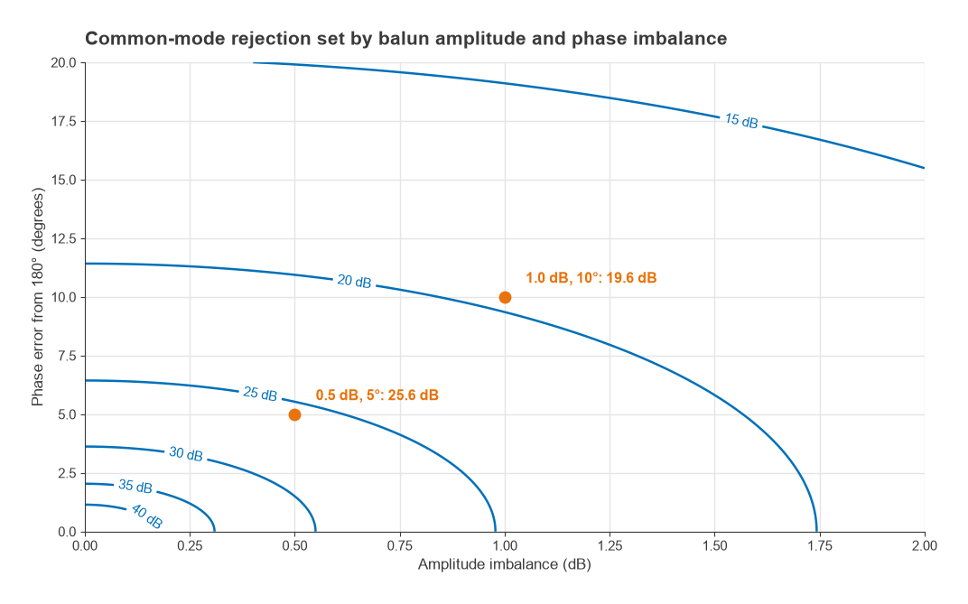
Here the common-mode term is taken as the sum V+ + V−. With 0.5 dB of amplitude imbalance and 5° of phase error, the CMRR is 25.6 dB. Amplitude imbalance alone at 0.5 dB gives 30.8 dB, and phase error alone at 5° gives 27.2 dB. Tightening both to 0.2 dB and 2° gives 33.6 dB, while 1 dB and 10° gives only 19.6 dB. Figure 3 maps the whole range. In a double-balanced mixer, that rejection sets how well LO and RF leakage and even-order products cancel. In a push-pull amplifier, it sets the second-harmonic suppression. For antenna feeds, the residual common mode sets how much current flows on the outside of the feed cable.
Choosing a balun type
| Type | Typical bandwidth | Size | Strengths | Limits |
|---|---|---|---|---|
| Ferrite or wire transformer | Several octaves, HF to low microwave | Small at HF, discrete part | Wide band, impedance ratio by turns, centre tap for DC | Core loss and parasitics limit high frequency |
| Marchand (coupled line) | About an octave or more | About λ/2 long | Good balance over wide band, planar, low loss | Large at low frequency, needs tight coupling |
| Lumped LC lattice | Roughly 10 to 20% for ±1 dB | Four small parts | Smallest, simple design equations, perfect ideal match | Narrowband, sensitive to component tolerance |
Ranges in the table are typical and depend on the design. Wideband instrumentation, antenna feeds at HF and push-pull amplifiers usually use transformers. Microwave mixers and planar front ends usually use Marchand baluns or their multilayer variants. Single-band radio modules often use lumped LC baluns or ceramic chip baluns between a differential transceiver and a single-ended antenna path, sometimes combined with the harmonic filter.
Frequently asked questions
What is a balun?
A balun is a passive network that converts between an unbalanced, ground-referenced signal and a balanced, differential one. It is used wherever a single-ended line meets a differential device, such as a dipole antenna, a balanced mixer or a differential ADC. Many baluns also transform impedance.
What is the difference between a current balun and a voltage balun?
A voltage balun forces equal and opposite voltages to ground at its balanced terminals. A current balun forces equal and opposite currents. With a perfectly symmetrical load both behave the same, but with an asymmetric load only the current balun keeps the currents balanced, which is why it is preferred for antenna feeds.
How do you design a lumped LC balun?
Compute Zm = √(R1R2) from the unbalanced and balanced resistances, then L = Zm/ω0 and C = 1/(ω0Zm). Build one low-pass arm (series L, shunt C) and one high-pass arm (series C, shunt L). For 50 Ω to 100 Ω at 2.45 GHz the values are 4.59 nH and 0.919 pF.
How much imbalance is acceptable?
It depends on the common-mode rejection the circuit needs. As a guide, about 0.5 dB and 5° gives roughly 25 dB of rejection, adequate for many mixers and antenna feeds. Applications that rely on cancellation of even-order products may need tighter balance.
Related topics
Baluns draw on several transmission line topics: types of transmission lines, line parameters and wave propagation. Closely related passive parts are hybrid couplers, which produce 90° or 180° splits, and the broader impedance matching techniques. Mixer applications are covered under mixer types, and terms are defined in the wireless terms glossary.