

A waveguide is a hollow metal tube, usually rectangular, that guides electromagnetic waves along its length without a centre conductor. Each mode it supports has a cutoff frequency below which it cannot propagate. For the dominant TE10 mode in a rectangular guide of broad-wall width a, the cutoff frequency is fc = c/(2a), so a WR-90 guide with a = 22.86 mm cuts off at 6.56 GHz.
Waveguides carry microwave and millimetre-wave power with lower loss and higher power handling than coaxial cable or printed lines, which is why they are still used in radar, satellite ground stations, high-power transmitters and test equipment above a few tens of gigahertz. This page belongs to the transmission lines section of the RF design guide. It derives the cutoff condition, explains TE10, lists the standard WR sizes and works through guide wavelength, wave impedance and loss for WR-90 at 10 GHz.
Why a Waveguide Has a Cutoff Frequency
A coaxial line or microstrip has two conductors and supports a TEM (or quasi-TEM) mode at any frequency down to DC. A hollow guide has only one conductor, so it cannot support TEM. Instead, the field inside can be pictured as plane waves bouncing between the walls at an angle. The walls force the tangential electric field to zero, which allows only certain transverse field patterns, the modes. Each mode needs the guide to be at least a certain fraction of a wavelength wide, which is the origin of the cutoff.
For a rectangular guide with inside dimensions a (broad wall) and b (narrow wall), filled with air, the cutoff frequency of the TEmn or TMmn mode is
fc,mn = (c/2) · √[(m/a)2 + (n/b)2]
where m and n are the number of half-wave variations of the field across the a and b dimensions. TE modes allow either index to be zero, but not both; TM modes need both indices to be at least 1. A dielectric filling with relative permittivity εr divides every cutoff by √εr.
Below cutoff the mode does not stop abruptly; it becomes evanescent and decays exponentially along the guide with attenuation constant α = kc√(1 − (f/fc)2), where kc = 2πfc/c. For WR-90 at 5 GHz, kc = π/a = 137.4 rad/m and α = 88.9 Np/m, which is 7.7 dB per centimetre. This rapid decay is what makes a short length of waveguide a very effective high-pass filter, and it is the principle behind waveguide-below-cutoff apertures used for ventilation in shielded rooms.
The TE10 Dominant Mode
Setting m = 1 and n = 0 gives the lowest cutoff of any mode when a > b:
fc,10 = c/(2a), λc = 2a
The guide must therefore be more than half a free-space wavelength wide for anything to propagate. The TE10 electric field is purely vertical (parallel to the narrow wall), with magnitude Ey = E0 sin(πx/a): zero at the side walls and maximum at the centre of the broad wall. The field does not vary with height, so the b dimension does not affect the TE10 cutoff at all. It does affect the cutoff of the TE01 mode, the power handling, and the loss.
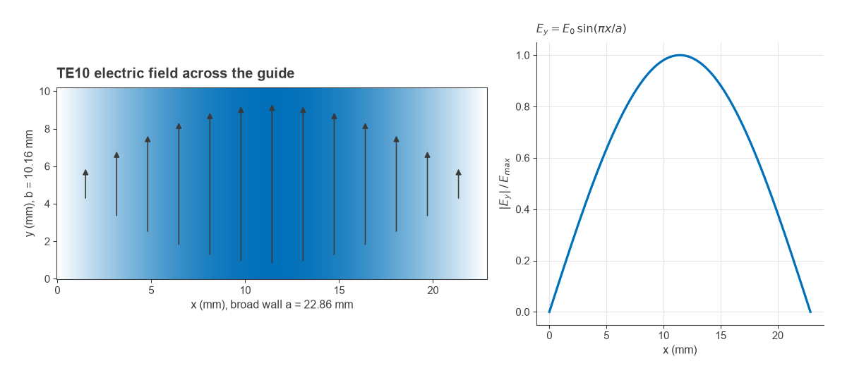
The magnetic field forms closed loops in the horizontal plane, and the wall currents follow from it. Along the centre line of the broad wall, the longitudinal current is zero, which is why a narrow slot cut there barely disturbs the mode. Slotted-line measurement sections use this property, while slots offset from the centre line couple strongly and are the basis of slotted-waveguide array antennas.
Single-mode operating band
Standard guides use a ≈ 2b. The next modes are then TE20 at c/a = 2fc,10 and TE01 at c/(2b), slightly above 2fc,10. In principle the guide is single-mode over an octave. In practice the recommended band runs from about 1.25 fc to about 1.9 fc. The lower margin avoids the steep rise in loss and dispersion close to cutoff; the upper margin keeps the second mode well below cutoff so that discontinuities cannot excite it.
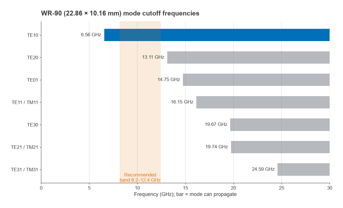
For WR-90 (22.86 × 10.16 mm) the mode cutoffs are 6.56 GHz for TE10, 13.11 GHz for TE20, 14.75 GHz for TE01 and 16.15 GHz for the degenerate TE11/TM11 pair. The standard band of 8.2 to 12.4 GHz is 1.25 to 1.89 times the TE10 cutoff.
Guide Wavelength, Phase Velocity and Wave Impedance
Above cutoff, the propagation constant of the mode is β = (2π/λ0)√(1 − (fc/f)2). Three useful quantities follow from it:
- Guide wavelength: λg = λ0 / √(1 − (fc/f)2), always longer than the free-space wavelength.
- Phase and group velocity: vp = c / √(1 − (fc/f)2) and vg = c · √(1 − (fc/f)2), with vp · vg = c2. Energy and information travel at vg, below c.
- TE wave impedance: ZTE = η0 / √(1 − (fc/f)2), where η0 ≈ 376.7 Ω.
Because vg depends on frequency, a waveguide is dispersive: a wideband signal spreads in time as it travels. This is negligible for narrowband links over short runs but matters for long feeds carrying wideband radar or communications signals. The general relationships between frequency, wavelength and velocity are covered in frequency and wavelength and wave propagation in transmission lines.
Worked example: WR-90 at 10 GHz
- Cutoff: fc = c/(2a) = 299.79 mm·GHz / 45.72 mm = 6.557 GHz.
- Free-space wavelength: λ0 = 299.79/10 = 29.98 mm.
- Ratio term: √(1 − (6.557/10)2) = √(1 − 0.430) = 0.755.
- Guide wavelength: λg = 29.98/0.755 = 39.7 mm, so a quarter guide wavelength is 9.93 mm.
- Velocities: vp = 1.324c and vg = 0.755c.
- Wave impedance: ZTE = 376.7/0.755 = 499 Ω.
The wave impedance is not the same thing as a circuit characteristic impedance. Waveguide matching is done with irises, posts and stubs, and transitions to coax use a probe or loop positioned to match the guide to 50 Ω; the result is still judged by VSWR and return loss.
Waveguide Loss
Loss in an air-filled guide comes from currents in the walls, which flow in a thin layer set by the skin effect. For TE10 the conductor attenuation is
αc = Rs (2bπ2 + a3k2) / (a3 b β k η0) (Np/m)
where Rs = √(πfμ0/σ) is the surface resistance and k = 2π/λ0. For WR-90 in copper (σ = 5.8 × 10⁷ S/m), this gives 0.140 dB/m at 8.2 GHz, 0.108 dB/m at 10 GHz and 0.097 dB/m at 12.4 GHz. These are ideal smooth-wall values; real guides with surface roughness, plating and flanges typically measure somewhat higher. Even so, the comparison with coaxial cable or a printed line of similar frequency, which is typically from one to several decibels per metre, explains why waveguide remains the choice for long, high-power or low-noise feeds. Loss mechanisms in other lines are compared in transmission line losses and power handling.
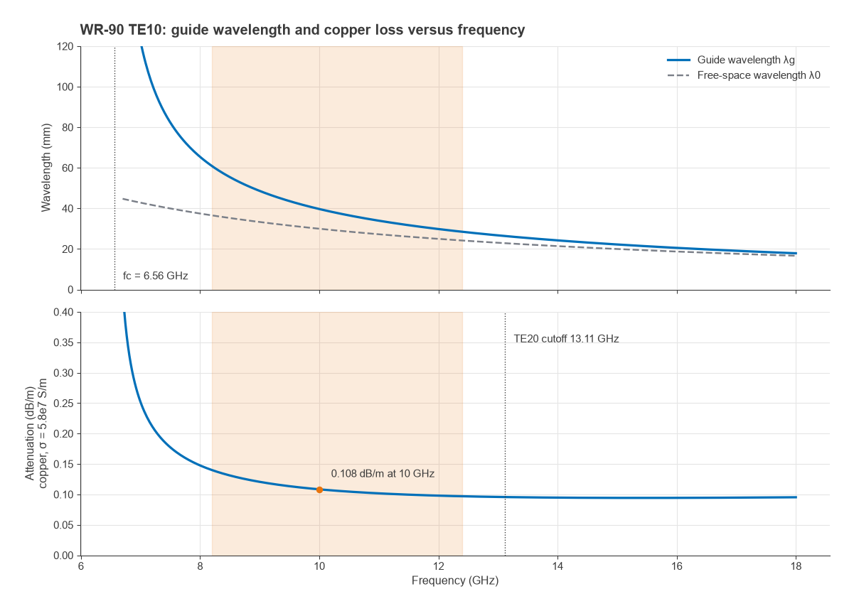
Loss rises steeply as the frequency approaches cutoff because the group velocity falls and the wave makes more wall reflections per metre of travel. That is one of the reasons the recommended band starts well above fc.
WR Waveguide Designations
Rectangular guides are identified by the EIA “WR” number, which is the inside broad-wall width in hundredths of an inch. WR-90 has a = 0.900 inch (22.86 mm); WR-28 has a = 0.280 inch (7.112 mm). Other systems, such as the IEC “R” designations, describe the same sizes with different labels. The table lists common sizes with nominal inside dimensions, the TE10 cutoff calculated from a, and the usual recommended operating band.
| Designation | Inside a × b (mm) | TE10 cutoff (GHz) | Recommended band (GHz) |
|---|---|---|---|
| WR-430 | 109.22 × 54.61 | 1.372 | 1.70 to 2.60 |
| WR-284 | 72.14 × 34.04 | 2.078 | 2.60 to 3.95 |
| WR-187 | 47.55 × 22.15 | 3.152 | 3.95 to 5.85 |
| WR-137 | 34.85 × 15.80 | 4.301 | 5.85 to 8.20 |
| WR-112 | 28.50 × 12.62 | 5.260 | 7.05 to 10.0 |
| WR-90 | 22.86 × 10.16 | 6.557 | 8.20 to 12.4 |
| WR-62 | 15.80 × 7.90 | 9.487 | 12.4 to 18.0 |
| WR-42 | 10.67 × 4.32 | 14.05 | 18.0 to 26.5 |
| WR-28 | 7.112 × 3.556 | 21.08 | 26.5 to 40.0 |
| WR-22 | 5.690 × 2.845 | 26.34 | 33.0 to 50.0 |
| WR-15 | 3.759 × 1.880 | 39.88 | 50.0 to 75.0 |
| WR-10 | 2.540 × 1.270 | 59.01 | 75.0 to 110 |
The bands correspond loosely to the letter bands used in radar and satellite work (WR-90 to X band, WR-62 to Ku band, WR-42 to K band, WR-28 to Ka band); see frequency bands in RF design. As frequency rises, the guide shrinks, wall loss per metre increases, and manufacturing tolerance becomes a larger fraction of the dimensions. Above about 110 GHz, guides are small enough that machining and flange alignment dominate performance.
Where Waveguides Are Used
Waveguide runs feed radar and satellite antennas, connect high-power transmitters to their loads, and form the ports of millimetre-wave test equipment. Waveguide components include directional couplers, circulators and isolators, filters built from resonant cavities and irises, and horn antennas. At millimetre-wave frequencies, waveguide interfaces also appear on chip packages and front-end modules, as described in Radio Architectures Part 19: mmWave radio architectures. Coaxial-to-waveguide adapters link these systems to the coaxial connectors used elsewhere.
On printed boards, the substrate-integrated waveguide (SIW) imitates a rectangular guide with two rows of vias in a laminate, and the same cutoff formula applies with the dielectric included and an effective width that accounts for via spacing. The name of coplanar waveguide is historical; it is a two-conductor planar line with no cutoff and behaves quite differently.
Frequently Asked Questions
What is the cutoff frequency of a waveguide?
It is the frequency below which a given mode cannot propagate and instead decays exponentially. For the dominant TE10 mode in an air-filled rectangular guide it is c/(2a), where a is the broad-wall width; for WR-90 that is 6.56 GHz.
What is TE10 mode?
TE10 is the transverse-electric mode with one half-wave variation of field across the broad wall and none across the narrow wall. It has the lowest cutoff in a standard rectangular guide, so it is the only mode that propagates in the normal operating band.
What does the WR number mean?
It is the inside broad-wall width in hundredths of an inch. WR-90 is 0.90 inch (22.86 mm) wide and WR-15 is 0.148 inch (3.759 mm) wide, so the number is a rounded value.
Why not operate a waveguide just above cutoff?
Close to cutoff the guide wavelength, wave impedance and loss change rapidly with frequency, and dispersion is high. Operating from about 1.25 fc keeps those effects moderate.
Related Topics
The transmission line theory hub links every line type on the site. For comparison with TEM lines see characteristics and types of transmission lines and transmission line parameters. Waveguide-fed antennas, such as horns, are part of antennas and propagation.