

A quadrature hybrid, or 90° hybrid coupler, is a four-port 3 dB directional coupler that splits an input signal into two equal-amplitude outputs 90° apart in phase, while the fourth port stays isolated. A 180° hybrid does the same with outputs in phase or in antiphase, depending on which port is driven. Both are lossless, reciprocal and matched at all ports when ideal.
Hybrids appear wherever two signals must be split or combined with a defined phase relationship: balanced amplifiers, image-reject and IQ mixers, beamforming networks and push-pull stages. This page belongs to the RF passive components section of the RF design guide. It covers the three classic realisations named in most textbooks, the branch-line, the Lange coupler and the rat-race, with their scattering matrices, design equations, simulated responses and a worked layout at 2.4 GHz.
What a Hybrid Coupler Does
A hybrid is a special case of the directional coupler with 3 dB coupling. Power entering one port divides equally between two output ports, the remaining port receives nothing, and the input is matched. Because the network is lossless and reciprocal, the same structure also works as a combiner: two signals with the right amplitude and phase relationship entering the output ports add at one port and cancel at the other.
Compared with a Wilkinson divider, which is a three-port with in-phase outputs and an internal resistor, a hybrid has four ports and dumps any imbalance into the isolated port. That fourth port can be terminated in 50 Ω or used as a second input. The behaviour is described compactly with S-parameters.
The 90° Branch-Line Hybrid
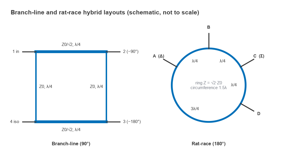
The branch-line hybrid is a square of four quarter-wave lines. Two opposite arms, the through arms, have impedance Z0/√2; the other two, the branch arms, have impedance Z0. With port 1 as input, port 2 is the through port, port 3 the coupled port and port 4 the isolated port. At the design frequency the scattering matrix is
[S] = −(1/√2) · [[0, j, 1, 0], [j, 0, 0, 1], [1, 0, 0, j], [0, 1, j, 0]]
A signal at port 1 therefore emerges at port 2 with a phase of −90° and at port 3 with −180°, each 3 dB below the input, with the two outputs in quadrature. The derivation splits the circuit into even-mode and odd-mode halves along its symmetry plane, each half reducing to a two-port with open or shorted λ/8 stubs. The same method appears in most microwave textbooks and is the clearest way to see why the impedances must be Z0/√2 and Z0.
Bandwidth of a single section
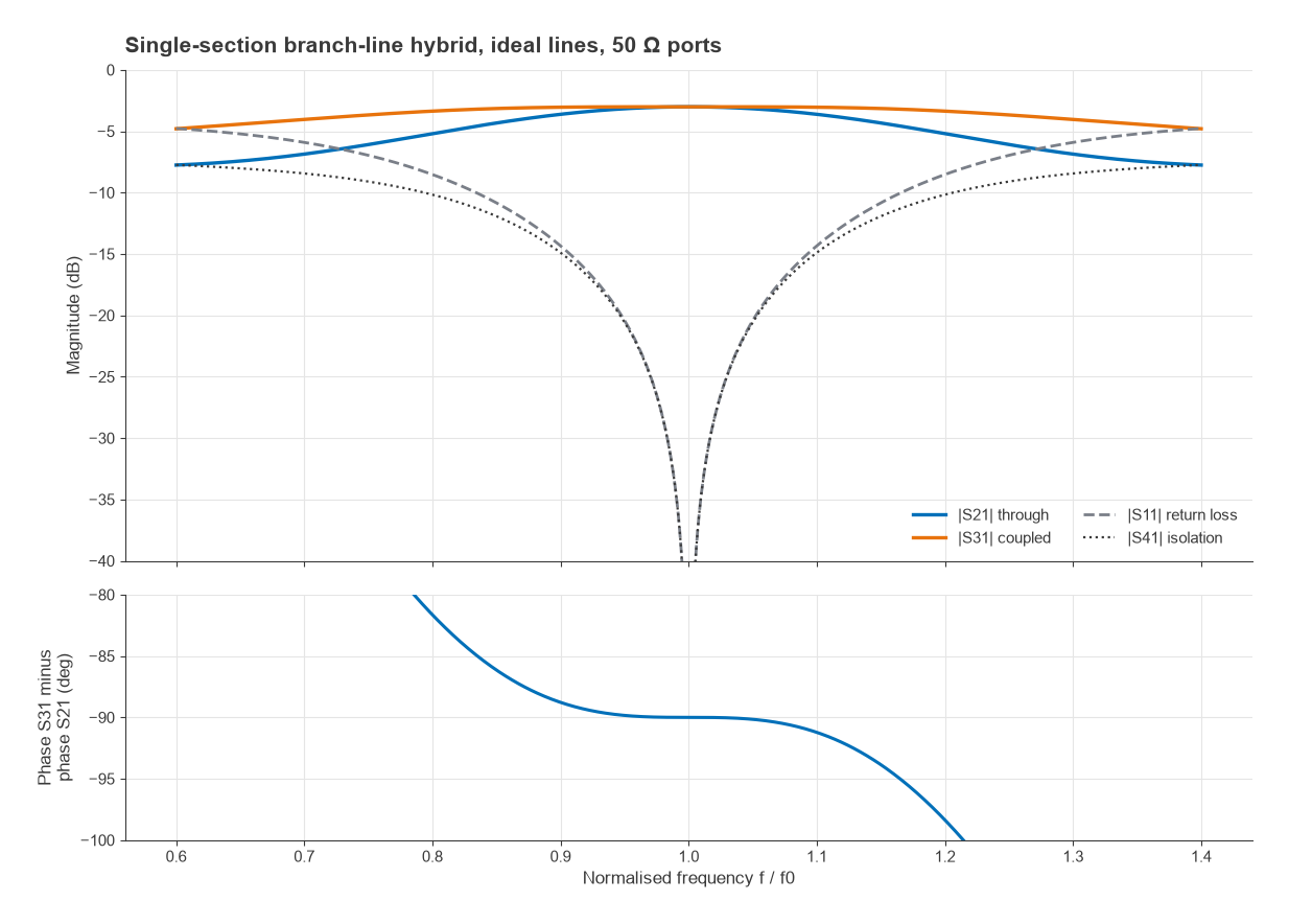
The quarter-wave lines are exact at only one frequency, so the branch-line is narrowband. A nodal simulation of ideal lines with 50 Ω ports gives these results:
- Return loss and isolation both better than 20 dB from 0.948 f0 to 1.052 f0, about 10 % fractional bandwidth.
- Amplitude imbalance between ports 2 and 3 below 0.5 dB from 0.908 f0 to 1.092 f0, about 18 %.
- Phase difference within 90° ± 2° from 0.882 f0 to 1.118 f0.
- At 0.9 f0, |S21| = −3.62 dB, |S31| = −3.04 dB, return loss 14.3 dB and isolation 14.9 dB.
The phase difference is the most forgiving quantity and the match and isolation the least. Cascading two or more branch-line sections with tapered impedances widens the band considerably, at the cost of size and of more extreme line impedances.
The Lange Coupler
A quarter-wave coupled-line coupler can, in principle, give 3 dB coupling with quadrature outputs over a much wider band than a branch-line. The difficulty is the coupling strength. For a single pair of coupled lines with voltage coupling factor C, the even- and odd-mode impedances are
Z0e = Z0 √[(1 + C)/(1 − C)], Z0o = Z0 √[(1 − C)/(1 + C)]
For 3 dB coupling, C = 0.707, which gives Z0e = 120.7 Ω and Z0o = 20.7 Ω in a 50 Ω system. Edge-coupled microstrip cannot reach an odd-mode impedance that low because the gap would have to be far narrower than PCB or thin-film processes allow. The Lange coupler solves this by splitting each line into several narrow interdigitated fingers, usually four, connected alternately with bond wires or air bridges. The extra edges multiply the coupling capacitance so that tight coupling becomes possible with realistic gaps.
Lange couplers typically cover an octave or more with good amplitude balance and are common in thin-film and MMIC circuits, especially balanced amplifiers. Their drawbacks are the fine geometry, the need for crossover connections, and sensitivity to process variation in the finger gaps. Unlike the branch-line, the coupled and through ports of a coupled-line hybrid sit on the same side of the structure, which suits balanced layouts.
The 180° Rat-Race Hybrid
The rat-race, or ring hybrid, is a loop of line 1.5 λ in circumference with impedance √2 · Z0 (70.7 Ω in a 50 Ω system). Four ports are spaced around it so that three adjacent sections are each λ/4 long and the fourth is 3λ/4. Label the ports A, B, C and D in order around the ring, with the 3λ/4 section between D and A.
- Feeding port C: the two paths to B differ by exactly one wavelength, as do the two paths to D, so B and D receive equal in-phase signals. The two paths to A differ by λ/2 and cancel, so A is isolated. Port C is the sum (Σ) port.
- Feeding port A: B and D again receive equal power, but now 180° apart, and C is isolated. Port A is the difference (Δ) port.
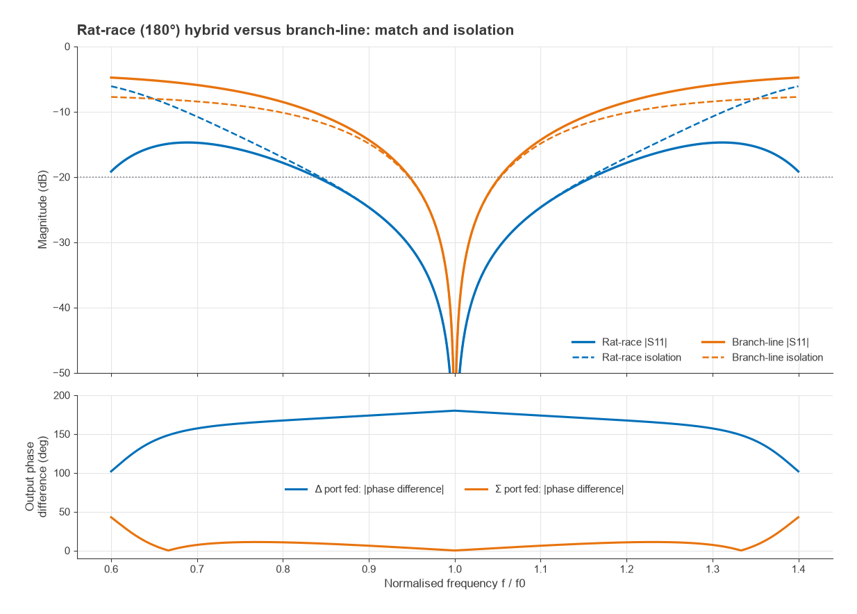
Used as a combiner, the rat-race delivers the sum of two inputs at Σ and their difference at Δ, which is exactly what monopulse radar comparators and balanced mixers require. Simulated with ideal lines, a single rat-race keeps return loss and isolation better than 20 dB from 0.844 f0 to 1.156 f0, about 31 %, which is wider than the single-section branch-line. When the Δ port is fed, the output phase difference moves away from 180° on either side of the centre frequency, reaching about 174° at 0.9 f0 and 167° at 0.8 f0.
Worked Example: Hybrids at 2.4 GHz
Consider a 50 Ω system at 2.4 GHz on a microstrip substrate with an effective permittivity of 3.3 (the exact value depends on the line width and laminate; use a microstrip calculator for each impedance).
- Free-space wavelength: λ0 = c/f = 299.79/2.4 = 124.9 mm.
- Guided wavelength: λg = λ0/√εeff = 124.9/√3.3 = 68.8 mm, so λg/4 = 17.2 mm.
- Branch-line: through arms 50/√2 = 35.4 Ω, branch arms 50 Ω, each about 17.2 mm long. In practice the 35.4 Ω and 50 Ω lines have slightly different εeff and therefore slightly different physical lengths, and the T-junction parasitics shorten them further.
- Rat-race: ring impedance 70.7 Ω, circumference 1.5 × 68.8 = 103.1 mm, giving a mean radius of 16.4 mm.
Both layouts occupy several square centimetres at 2.4 GHz, which is why lower-frequency designs often use lumped-element equivalents (each quarter-wave line replaced by a pi or tee of inductors and capacitors) or meandered lines. At millimetre-wave frequencies the opposite problem arises: the lines become short enough that junction effects dominate and full-wave simulation is needed.
Choosing Between Hybrid Types
| Type | Output phase | Bandwidth (single section) | Realisation | Typical uses |
|---|---|---|---|---|
| Branch-line | 90° | About 10 % for 20 dB match and isolation | Microstrip or stripline, simple | Balanced amplifiers, IQ splitting, circular polarisation feeds |
| Lange | 90° | Octave or more, typical | Interdigitated fingers with bond wires or air bridges | MMIC and thin-film balanced amplifiers |
| Rat-race | 0° or 180° | About 30 % for 20 dB match and isolation | Microstrip ring, simple | Balanced mixers, sum/difference networks, push-pull |
| Transformer hybrid | 0° or 180° | Decades at HF and VHF | Ferrite-cored windings | HF and VHF push-pull amplifiers, combiners |
Applications
In a balanced amplifier, an input quadrature hybrid feeds two identical amplifiers and an output hybrid recombines them. Reflections from the two amplifier inputs arrive at the isolated port in phase and at the input port in antiphase, so the overall input match is good even when each amplifier is deliberately mismatched for best noise figure or gain flatness. The same idea underlies many broadband amplifier designs.
Quadrature hybrids create the 90° LO or IF split in IQ modulators and demodulators and in image-reject mixers. 180° hybrids drive double-balanced mixers and act as baluns. Networks of 90° hybrids and fixed phase shifters form Butler matrices that produce multiple fixed beams from an array, one of the topics in MIMO, beamforming and phased arrays.
Frequently Asked Questions
What is a quadrature hybrid?
It is a four-port 3 dB coupler whose two outputs have equal amplitude and a 90° phase difference, with the fourth port isolated. The branch-line and Lange couplers are the most common forms.
What is the difference between a 90° and a 180° hybrid?
A 90° hybrid always produces outputs in quadrature. A 180° hybrid produces in-phase outputs when fed at the sum port and antiphase outputs when fed at the difference port, which makes it suitable for sum and difference networks and balanced mixers.
What should be connected to the isolated port?
Usually a matched load rated for the worst-case power that imbalance or reflections could send there. In a balanced amplifier, that load absorbs the reflected power from the two amplifier inputs, so its rating matters if one amplifier fails.
How can a branch-line hybrid be made smaller?
Meander the quarter-wave lines, replace them with lumped LC equivalents, or use a higher-permittivity substrate. Each option trades size against loss, bandwidth or tolerance sensitivity.
Related Topics
The RF passive components hub links the related building blocks: directional couplers, Wilkinson dividers, attenuators and circulators and isolators. The quarter-wave line theory behind every hybrid is in transmission line theory.