

A good LNA noise figure is one that is small compared with the noise already arriving from the antenna. Below about 1 dB is typical for satellite, GNSS and other cold-sky receivers, while 1 to 3 dB is usually ample for terrestrial VHF and UHF links where man-made and atmospheric noise dominate. Choosing an LNA means balancing that noise figure against gain, linearity (OIP3 and P1dB), bandwidth, filtering and how the amplifier is powered and placed.
This guide works through those decisions in the order an engineer usually meets them. It assumes the noise and linearity background from the noise figure and linearity sections, and it complements the circuit-level treatment in Low Noise Amplifier Design. It is part of the RF amplifiers section.
The Decision Table
The table lists the specifications that decide most LNA choices, what each one controls, and roughly where the useful range lies. The ranges are approximate guides drawn from common practice, not limits from any standard.
| Specification | What it controls | How to choose |
|---|---|---|
| Noise figure (NF) | Sensitivity of the whole receiver | Compare with antenna noise temperature. Roughly 0.3 to 1 dB for cold-sky and GNSS use; 1 to 3 dB is often adequate for terrestrial links. |
| Gain | How far the LNA suppresses noise from the cable and receiver | Enough to exceed cable loss plus receiver NF by about 10 dB; more only adds overload risk. |
| OIP3 / IIP3 | Intermodulation from strong nearby signals | Set by the strongest expected interferers. Higher is better near broadcast, cellular or radar transmitters. |
| P1dB | Level at which the LNA starts to compress | Should sit well above the largest total signal power at the LNA output. |
| Bandwidth and filtering | Which signals the LNA amplifies, wanted or not | No wider than needed; a filtered LNA where strong out-of-band signals are present. |
| Input and output match | Mismatch loss and cable ripple | Return loss of roughly 10 dB or better at both ports, unless the LNA is deliberately noise-matched. |
| Supply and bias feed | How the LNA is powered at the antenna | Check voltage range, current and whether it accepts DC through the coax via a bias tee. |
| Survivability | Damage from nearby transmitters or static | Check the maximum input power rating and whether a limiter is built in. |
Noise Figure: How Low Is Low Enough?
Noise figure only matters relative to the noise the antenna already delivers. Converting the LNA’s noise figure to an equivalent noise temperature, Te = 290(F − 1) K, the system noise temperature is approximately
Tsys = Tant + Te
An LNA with NF = 0.5 dB has Te = 35.4 K, and one with NF = 1.5 dB has Te = 119.6 K. If the antenna sees a 290 K environment, the system temperatures are 325.4 K and 409.6 K, a difference of only 1.0 dB in noise floor. If the antenna points at a cold sky with Tant = 50 K, they are 85.4 K and 169.6 K, a difference of 3.0 dB. The same 1 dB of LNA noise figure is worth three times as much in the second case. This is why satellite and radio-astronomy receivers chase fractions of a dB, while HF and many VHF receivers gain little from an LNA at all.
Where the LNA Goes: Placement and the Friis Formula
The Friis formula for cascaded noise factor,
Ftotal = F1 + (F2 − 1)/G1 + (F3 − 1)/(G1G2) + …
shows that the first stage counts in full and every later stage is divided by the gain in front of it. A passive cable with loss L has noise factor F = L (linear) and gain 1/L, so a lossy cable in front of the LNA adds its whole loss to the system noise figure. The LNA belongs at the antenna end of the cable. The derivation is on the cascaded noise figure page.
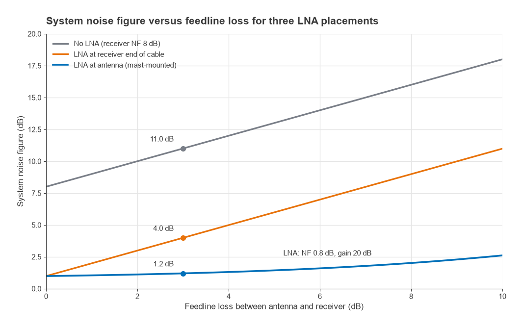
Worked example: mast LNA versus receiver-end LNA
A receiver has NF = 8 dB (F = 6.31). It is fed through coax with 3 dB loss (F = 2.0, G = 0.5). The LNA has NF = 0.8 dB (F = 1.202) and 20 dB gain (G = 100).
- No LNA: F = 2.0 + (6.31 − 1)/0.5 = 12.6, so NF = 11.0 dB.
- LNA at the receiver end: F = 2.0 + (1.202 − 1)/0.5 + (6.31 − 1)/(0.5 × 100) = 2.0 + 0.404 + 0.106 = 2.51, so NF = 4.0 dB.
- LNA at the antenna: F = 1.202 + (2.0 − 1)/100 + (6.31 − 1)/(100 × 0.5) = 1.202 + 0.010 + 0.106 = 1.318, so NF = 1.2 dB.
Moving the same LNA from the receiver to the antenna improves the system noise figure by 2.8 dB, and the improvement grows with cable loss. With 6 dB of cable the three cases become 14.0 dB, 7.0 dB and 1.6 dB. Whenever the feedline loss is more than a fraction of a dB, a mast-mounted LNA is the better choice.
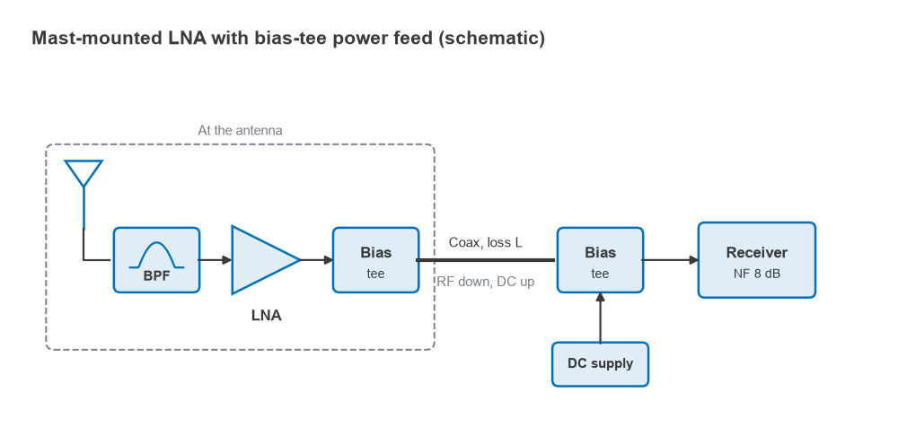
A mast-mounted LNA needs power at the antenna. The usual method is a bias tee at each end of the coax, one injecting DC at the receiver and one extracting it at the LNA, as in Figure 2. Many GNSS receivers and SDRs can supply this voltage themselves. Check the voltage, the current limit and whether the receiver input tolerates DC before connecting anything. Bias tees are covered in Biasing RF Transistors and MMICs.
How Much Gain Do You Need?
Gain is the lever that makes the later terms of the Friis formula small. A practical target is that the LNA gain should exceed the cable loss plus the receiver’s noise figure by around 10 dB. Figure 3 shows a mast LNA feeding 6 dB of cable into a receiver with 8 dB NF. With an LNA of 0.5 dB NF, the system noise figure is 5.5 dB at 10 dB gain, 1.35 dB at 20 dB gain and 0.59 dB at 30 dB gain. Above roughly 25 to 30 dB the curve is flat, and extra gain buys nothing.
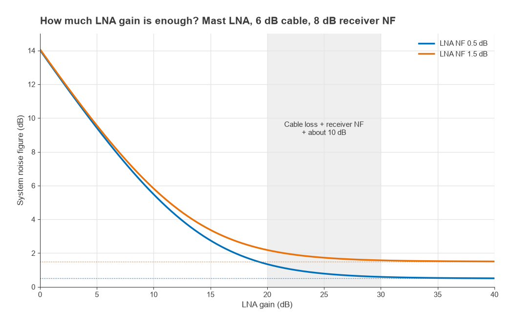
Extra gain is not free. It raises every signal at the receiver input, including strong ones, and pushes the receiver or its ADC towards compression and intermodulation. Every dB of gain beyond what the noise calculation needs lowers the receiver’s overload point referred to the antenna by one dB. If a high-gain LNA is the only option, an attenuator at the receiver end restores the balance. Overall gain distribution is the same trade-off shown in the amplifier hub, where the stage after the LNA sets most of the distortion.
Linearity: OIP3 and P1dB
The LNA sees every signal the antenna collects, not only the wanted one. Two strong signals at f1 and f2 produce third-order products at 2f1 − f2 and 2f2 − f1, and if those land on the wanted channel they cannot be filtered out afterwards. The input-referred product level is
PIM3,in = 3Pin − 2·IIP3
For P1dB, the relevant number is the total power of all signals reaching the LNA, not the wanted signal alone. A wideband LNA near a broadcast transmitter can be driven into compression by a signal hundreds of MHz away from the band of interest. The P1dB and intermodulation pages give the full background.
Filtered Versus Unfiltered LNAs
A filtered LNA places a bandpass filter before the amplifier, after it, or both. A filter before the LNA protects it from strong out-of-band signals but adds its insertion loss directly to the noise figure. A filter after the LNA keeps the noise figure low but protects only the following stages. Designs for hostile environments often use a low-loss pre-filter followed by a sharper post-filter.
Worked example: when a pre-filter pays for itself
An LNA with IIP3 = +5 dBm and NF = 1 dB serves a receiver with 1 MHz bandwidth. Its noise floor is −174 + 10log(106) + 1 = −113 dBm. Two out-of-band interferers arrive at equal power and are spaced so that one IM3 product falls in the channel.
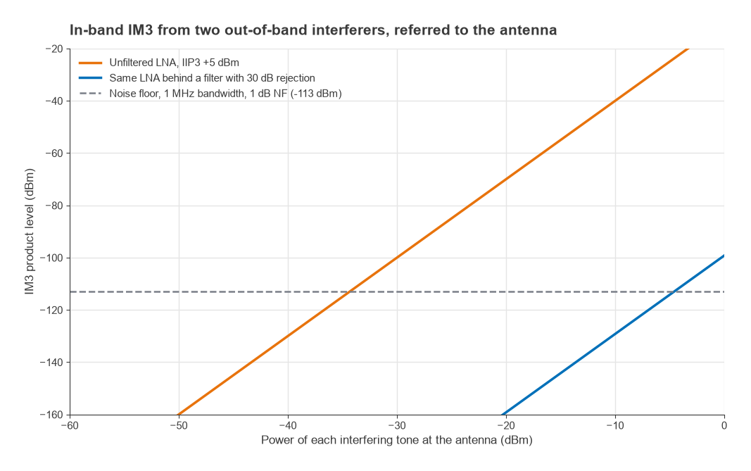
- Without a filter, the product reaches the noise floor when 3Pin − 10 = −113, so Pin = −34.3 dBm per tone.
- With a pre-filter giving 30 dB of rejection at the interferer frequencies and 0.8 dB in-band loss, the tones reach the LNA 30 dB lower, and the IM3 product falls by 90 dB. The tones must now be about −4.6 dBm at the antenna before the product reaches the floor.
- The cost is 0.8 dB of extra noise figure, from about 1 dB to about 1.8 dB.
The filter trades 0.8 dB of sensitivity for roughly 30 dB more tolerance to interference. Near cellular base stations, broadcast towers, airports or co-located transmitters, that trade is almost always worth making. At a quiet rural site with a cold-sky antenna, the unfiltered LNA with its lower noise figure may be the better choice. Filter types are compared in the RF filters section.
Bandwidth, Match and Stability
A wideband LNA is convenient for a multi-band receiver, but every extra MHz of bandwidth is another place for a strong signal to enter. Choose the narrowest bandwidth that covers the wanted signals. Check that the LNA is unconditionally stable, because an antenna presents a source impedance that changes with frequency, weather and nearby objects, and an LNA that is only conditionally stable can oscillate when connected to it.
Selection Checklist
- Frequency range covers the wanted band with margin, and no more than necessary.
- Noise figure is low compared with the antenna noise temperature for this application.
- Gain exceeds cable loss plus receiver NF by about 10 dB, without overloading the receiver.
- IIP3 and P1dB comfortably exceed the strongest expected signals at the site.
- A filtered version is used where strong out-of-band transmitters are nearby.
- The LNA is mounted at the antenna if the feedline has more than a fraction of a dB of loss.
- Supply voltage and current suit the available bias-tee feed, and the receiver tolerates DC on its input if it supplies it.
- The maximum input power rating survives nearby transmitters, with a limiter added if needed.
- Connectors and weatherproofing suit an outdoor mount.
Frequently asked questions
What is a good LNA noise figure?
It depends on the antenna noise. For GNSS, satellite and other receivers looking at a cold sky, something below about 1 dB is typical. For terrestrial VHF and UHF systems where the antenna sees a warm, noisy environment, 1 to 3 dB is usually enough, because a lower figure barely changes the system noise temperature.
How much LNA gain do I need?
Enough to exceed the cable loss plus the receiver’s noise figure by about 10 dB. With 6 dB of cable and an 8 dB receiver that means roughly 24 dB. Beyond that, extra gain does not improve sensitivity and reduces the receiver’s tolerance to strong signals.
Where should the LNA go in the chain?
As close to the antenna as possible, before any significant cable loss. In the worked example above, moving the LNA from the receiver end of a 3 dB cable to the antenna lowers the system noise figure from 4.0 dB to 1.2 dB.
Do I need a filtered LNA?
If strong transmitters operate near your band or near your site, yes. A pre-filter adds its insertion loss to the noise figure but can raise interference tolerance by tens of dB. In a quiet environment an unfiltered LNA gives the lowest noise figure.
Related topics
For practical front ends for software-defined radios, see LNA setup for SDR, ADS-B and GNSS. For amplifiers used after the LNA, see How to Choose a Broadband RF Amplifier. Receiver sensitivity calculations are covered in Radio Architectures Part 4, and the wider context is in the RF design reference.