

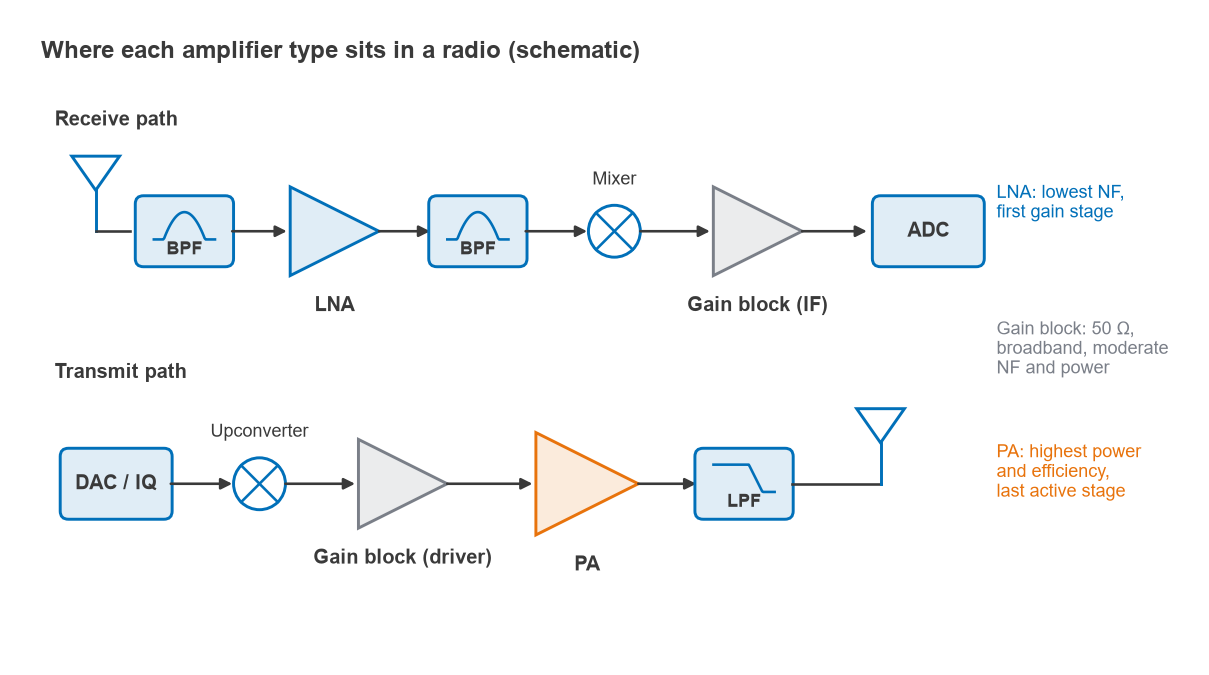
An LNA, a gain block and a power amplifier are all RF amplifiers, but each is optimised for a different figure of merit. A low-noise amplifier minimises noise figure so it can amplify weak received signals first in the chain. A power amplifier maximises output power and efficiency so it can drive the antenna last in the transmit chain. A gain block is a general-purpose, internally matched 50 Ω amplifier that trades some of both for convenience and bandwidth.
Choosing between them is one of the first decisions in any RF design, and the RF amplifiers section covers each type in depth. This page compares the three by noise figure, compression point, efficiency and position in the chain, and works through what goes wrong when one is used in the other’s place.
Three amplifiers, three jobs
Low-noise amplifier (LNA)
The LNA’s job is to add as little noise as possible while providing enough gain that later stages do not matter much. Its input is matched not for maximum power transfer but for minimum noise, which means presenting the transistor with its optimum source reflection coefficient Γopt. The two goals differ, so an LNA’s input return loss is often a compromise. Gain is moderate, linearity is modest, and power consumption is usually small. The design process is covered in design of radio low-noise amplifiers.
Gain block
A gain block is usually a resistive-feedback or Darlington amplifier, internally matched to 50 Ω at input and output over a wide band, often from tens of megahertz to several gigahertz. It needs only DC blocking capacitors and a bias feed. The feedback that gives it flat gain and good match also adds noise and limits efficiency. Gain blocks are used as IF amplifiers, LO buffers, transmit drivers and in test setups. Broadband amplifier design is covered in broadband RF amplifier design.
Power amplifier (PA)
A PA delivers the transmit power to the antenna. Its output is matched to the load line that gives the required power and efficiency, found by load-pull rather than by conjugate matching, so its small-signal output return loss can look poor. PAs operate in classes from linear class A and AB to switching classes such as E and F, described in power amplifier classes. Efficiency, thermal design and linearity under modulation dominate the design. Noise figure is rarely specified because the signal is already large.
Comparison table: NF, P1dB, efficiency and position in the chain
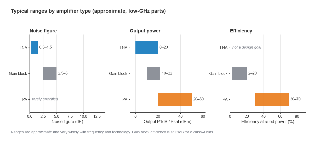
The ranges below are typical for low-gigahertz parts and are approximate. They vary widely with frequency, semiconductor technology and bandwidth, and any real design should use datasheet values. Reading those values correctly is covered in how to read an RF amplifier datasheet.
| Parameter | LNA | Gain block | Power amplifier |
|---|---|---|---|
| Primary goal | Lowest noise figure | Flat gain, 50 Ω match, ease of use | Output power and efficiency |
| Noise figure | About 0.3 to 1.5 dB | About 2.5 to 5 dB | Rarely specified |
| Gain per stage | About 12 to 25 dB | About 12 to 22 dB | About 10 to 35 dB (multi-stage) |
| Output P1dB or Psat | About 0 to +20 dBm | About +10 to +22 dBm | About +20 to +50 dBm and above |
| Efficiency at rated power | Not a design goal | About 2 to 20% (class A) | About 30 to 70% (PAE, class dependent) |
| Bandwidth | Narrow to moderate | Very wide, often multi-octave | Usually narrow, set by output match |
| Input match | Noise match (Γopt) | 50 Ω internal | Gain or stability match |
| Output match | Gain or 50 Ω | 50 Ω internal | Load-line from load-pull |
| Position in chain | First active stage in receiver | Middle: IF, LO, driver | Last active stage in transmitter |
Two points from the table matter most. Noise figure spans roughly an order of magnitude between an LNA and a gain block. Output power spans several orders of magnitude between a gain block and a PA. Neither gap can be closed by adjusting bias or matching on the wrong part.
Why the LNA goes first: a Friis example
The Friis formula gives the cascaded noise factor of a chain of stages with noise factors Fn and gains Gn (linear):
Ftotal = F1 + (F2 − 1)/G1 + (F3 − 1)/(G1G2) + …
The first stage’s noise adds directly, and every later stage is divided by the gain ahead of it. That is the case for putting the lowest-noise, adequate-gain stage first, as explained in detail in cascaded noise figure.
Worked example: swapping the LNA and the gain block
Take a receiver front end with a preselect filter (1 dB loss), an LNA (NF 1.0 dB, gain 18 dB), a gain block (NF 4.5 dB, gain 15 dB) and a mixer (NF 10 dB, conversion loss 7 dB).
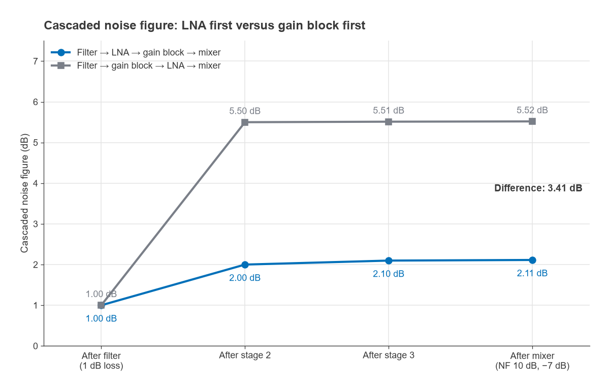
- LNA first. After the filter, F = 1.259 (1.00 dB). Adding the LNA: 1.259 + (1.259 − 1)/0.794 = 1.585, or 2.00 dB. Adding the gain block: 1.585 + (2.818 − 1)/(0.794 × 63.1) = 1.621, or 2.10 dB. Adding the mixer brings the total to 2.11 dB.
- Gain block first. After the filter and gain block: 1.259 + (2.818 − 1)/0.794 = 3.548, or 5.50 dB. The LNA and mixer that follow barely change it: the total is 5.52 dB.
The difference is 3.41 dB of noise figure, which translates directly into 3.41 dB of receiver sensitivity. In a link budget, that is roughly the same as losing a third of the range in free space, since range scales with the square root of received power. Once the gain block is first, no later LNA can recover the loss.
The order has a cost on the linearity side. A high-gain first stage raises the signal level seen by later stages, so the mixer’s intercept point becomes more important. Front-end designers balance noise figure against intermodulation performance, and in environments with strong nearby transmitters a slightly lower-gain LNA can give a better overall result.
Why a gain block is not a power amplifier
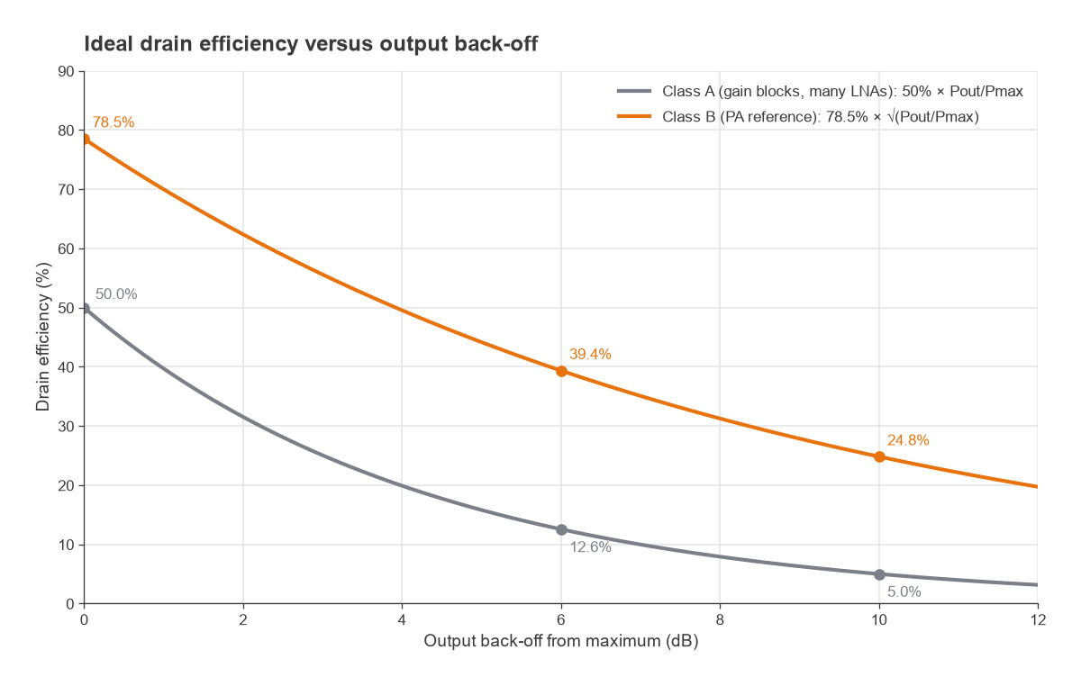
Gain blocks are biased in class A, where the transistor conducts over the whole RF cycle. The ideal class A drain efficiency at maximum swing is 50%, and it falls in direct proportion to output power as the signal backs off:
ηA = 50% × (Pout / Pmax)
An ideal class B stage reaches π/4 = 78.5% at full swing and falls only with the square root of power:
ηB = 78.5% × √(Pout / Pmax)
At 6 dB back-off these give 12.6% and 39.4%; at 10 dB, 5.0% and 24.8%. Real parts fall below these ideal curves, but the trend is the reason PAs use class AB or more efficient classes and why linearization techniques exist to run them closer to saturation.
Worked example: DC power for 1 W output
A PA delivering 1 W (+30 dBm) with 30 dB of gain needs 1 mW of drive. At a power-added efficiency of 40%, the DC input is PDC = (Pout − Pin) / PAE = (1 − 0.001) / 0.40 = 2.50 W, and the heat to remove is PDC + Pin − Pout = 1.50 W.
Now consider using gain blocks instead. A typical gain block with an output P1dB around +20 dBm (100 mW) cannot reach 1 W at all, and even running at its own compression point with, say, 0.4 W of DC bias it is only 25% efficient. Ten of them combined would need a combining network with its own loss and would still be less efficient, and far larger, than one PA. Conversely, a PA used as a small-signal amplifier wastes most of its bias current and usually has a poor input match and high noise figure.
Where each type is used
- LNA: receiver front ends, GNSS and satellite receivers, radio astronomy, and SDR front ends where the built-in receiver noise figure is high (see LNA for SDR).
- Gain block: IF strips, LO distribution and buffering, transmit driver stages, making up loss in cables and splitters, and general laboratory use.
- PA: the final stage of transmitters, from milliwatt IoT radios to kilowatt broadcast and radar systems.
The lines blur at the edges. Some LNAs are built from gain-block-style feedback topologies for wide bandwidth, and some gain blocks reach +24 dBm or more and serve as low-power PAs. The deciding question is which parameter the application cannot compromise on. Neutral selection procedures are covered in how to choose an LNA and how to choose a broadband RF amplifier.
Frequently asked questions
What is the difference between an LNA and a PA?
An LNA is optimised for the lowest noise figure and sits first in a receiver, handling very weak signals. A PA is optimised for high output power and efficiency and sits last in a transmitter, driving the antenna. Their matching networks, bias points and transistor sizes differ accordingly.
Can a gain block be used as an LNA?
It can amplify, but its noise figure is typically several dB higher than a dedicated LNA. In the worked example above, putting a gain block first cost 3.4 dB of sensitivity. Where noise figure is not critical, such as after an LNA or in a strong-signal path, a gain block is often the simpler choice.
What is P1dB and why does it matter for these amplifiers?
P1dB is the output power at which gain has dropped 1 dB below its small-signal value. It marks the onset of compression and sets how large a signal each amplifier can handle. The concept is explained in P1dB compression point.
Related topics
Bias networks for all three types are covered in RF amplifier biasing, and the semiconductor choices behind them in RF transistor technologies. Terms used on this page are defined in the wireless terms glossary.