

RF PCB substrates are the dielectric laminates that set a board’s impedance, loss and phase stability, and they range from low-cost glass-epoxy FR-4 to ceramic-filled hydrocarbon and PTFE laminates sold by Rogers and others. You can use FR-4 for RF when lines are short and the frequency is below a few gigahertz; above that, or where loss, phase accuracy or repeatability matter, a controlled RF laminate pays for itself.
The choice comes down to three material properties and one budget. The dielectric constant (Dk, or εr) sets trace widths and electrical length. The dissipation factor (Df, or tan δ) sets dielectric loss. The tolerance and frequency stability of Dk set how closely the built board matches the design. Cost and manufacturability decide how much of the board uses the better material. This page belongs to the RF PCB layout section.
Dk, Df and Tolerance Compared
The table gives typical values for common laminate families. Figures for the named grades are approximate datasheet values as of 2026 and are given for comparison only; always design with the current datasheet and the fabricator’s stackup data. FR-4 covers a wide family of glass-epoxy products, and its values vary with resin content, glass style and supplier.
| Material | Dk near 1 GHz | Dk near 10 GHz | Df near 10 GHz | Dk tolerance |
|---|---|---|---|---|
| Standard FR-4 | about 4.2 to 4.5 | about 4.0 to 4.3 | about 0.015 to 0.025 | often not specified; ±0.2 or more in practice |
| Low-loss epoxy blends | about 3.6 to 4.0 | slightly lower | about 0.005 to 0.010 | varies by product |
| Hydrocarbon ceramic, RO4350B class | 3.48 (process), 3.66 (design) | 3.48 (process), 3.66 (design) | about 0.0037 | ±0.05 |
| Hydrocarbon ceramic, RO4003C class | 3.38 (process), 3.55 (design) | 3.38 (process), 3.55 (design) | about 0.0027 | ±0.05 |
| PTFE glass microfibre, RT/duroid 5880 class | 2.20 | 2.20 | about 0.0009 | ±0.02 |
Two details in the table matter in practice. First, FR-4’s Dk falls noticeably with frequency, by several percent from 1 MHz to 10 GHz, while RF laminates are specified to stay nearly flat. A board designed with a 1 MHz Dk figure from a generic FR-4 datasheet will have lines that run slightly wide and long at microwave frequencies. Second, RF laminate vendors often quote a “process” Dk measured on bare material and a “design” Dk extracted from real microstrip circuits. The design value is the one to use for impedance and phase calculations.
How Df Turns Into Insertion Loss
Microstrip loss has a dielectric part and a conductor part. The dielectric part, in dB per metre, is
αd = 27.3 · [εr / √εeff] · [(εeff − 1)/(εr − 1)] · tan δ / λ0
where λ0 is the free-space wavelength in metres. It rises in proportion to frequency. Conductor loss rises with the square root of frequency through the skin-effect surface resistance Rs = √(πfμ0/σ); for a wide strip it is roughly αc ≈ 8.686 Rs/(Z0W) dB per metre. The skin effect page explains why copper roughness adds to this at high frequency.
Worked example: a 100 mm line on three laminates
Take a 50 Ω microstrip, 100 mm long, on a 0.508 mm dielectric with smooth copper. The line widths come out at about 1.00 mm on FR-4 (Dk 4.3), 1.12 mm on a RO4350B-class laminate (design Dk 3.66) and 1.58 mm on PTFE (Dk 2.20).
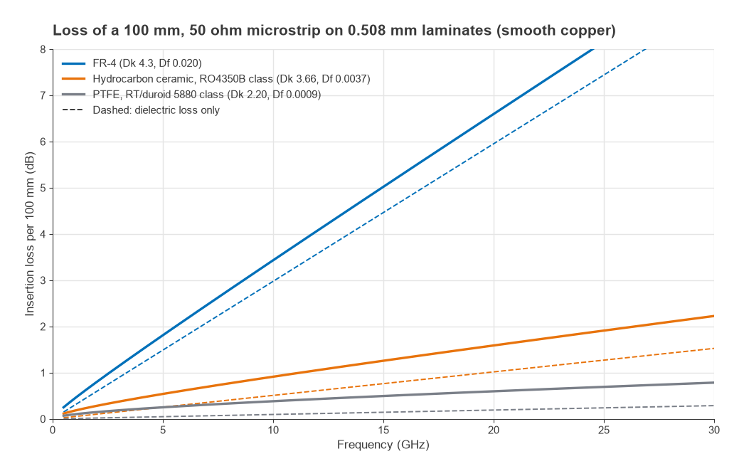
| Frequency | FR-4, Df 0.020 | Hydrocarbon ceramic, Df 0.0037 | PTFE, Df 0.0009 |
|---|---|---|---|
| 2.4 GHz | 0.94 dB | 0.32 dB | 0.16 dB |
| 5.8 GHz | 2.07 dB | 0.60 dB | 0.27 dB |
| 10 GHz | 3.43 dB | 0.91 dB | 0.38 dB |
| 28 GHz | 9.09 dB | 2.10 dB | 0.75 dB |
At 2.4 GHz on FR-4, 0.71 dB of the 0.94 dB is dielectric loss. For a 10 mm feed from a radio IC to an antenna, that is under 0.1 dB, which is why FR-4 is common in short-range sub-6 GHz products. For a 100 mm line at 10 GHz, or any line at 28 GHz, FR-4 loses several decibels and the choice is no longer close. Real boards lose somewhat more than these smooth-copper figures because of copper roughness, solder mask and radiation.
Why Dk Tolerance Matters
A line’s impedance changes only slowly with Dk. A trace drawn for 50 Ω at Dk 4.3 measures about 51.7 Ω if the real Dk is 4.0 and 48.5 Ω if it is 4.6. Electrical length is more sensitive, because it scales with √εeff. A quarter-wave resonator designed for 5.8 GHz on FR-4 with a nominal Dk of 4.3 resonates anywhere from about 5.63 GHz to 5.99 GHz over the 4.0 to 4.6 range. On a laminate held to ±0.05 around 3.66, the same resonator stays within about 5.76 to 5.84 GHz.
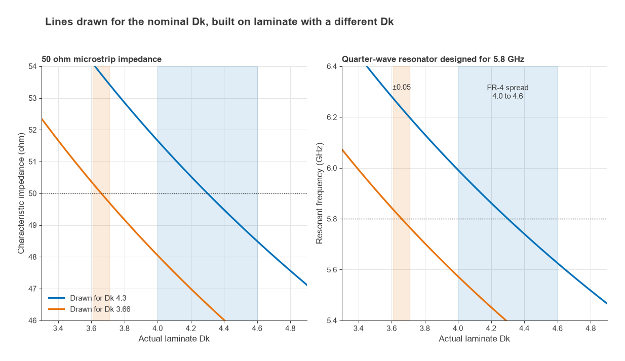
That spread is what decides the material for microstrip filters, couplers, Wilkinson dividers, patch antennas and phase-matched feeds for phased arrays. A filter whose passband moves by 3% between production lots, or an array whose element phases differ by tens of degrees, cannot be fixed by tuning. Broadband amplifiers and short interconnects, by contrast, hardly notice.
Can You Use FR-4 for RF?
Yes, and most high-volume products below about 6 GHz do. FR-4 is a sensible choice when:
- RF lines are short, a few centimetres at most, so loss is a fraction of a decibel.
- The frequency-selective parts are bought-in components such as SAW or LC filters, not printed structures.
- A matching network on the board can absorb small impedance and length errors.
- The fabricator specifies the stackup and impedance-controls the RF lines, so Dk variation is at least characterized.
FR-4 is less suitable for printed filters and couplers above 1 to 2 GHz, long low-loss feed lines, high-power amplifier output networks where dielectric heating matters, and almost anything at millimetre-wave frequencies.
When You Need Rogers or Another RF Laminate
- Hydrocarbon ceramic laminates (the RO4000 family and similar products) are the common step up. They offer low Df, tight Dk tolerance and, for many grades, processing similar to FR-4. They suit most microwave PCBs up to roughly 20 to 30 GHz.
- PTFE-based laminates have the lowest loss and Dk around 2.2 to 3.0. They are used for millimetre-wave circuits, low-loss antennas and space or defence hardware. PTFE is soft and needs special drilling and hole preparation, which raises fabrication cost and narrows the list of capable fabricators.
- High-Dk ceramic-filled laminates (Dk of about 6 to 10) shrink circuit size at lower frequencies, at the cost of narrower lines and tighter etch tolerance.
Thermal properties also differ. The temperature coefficient of Dk shifts filter centre frequencies with temperature, and the coefficient of thermal expansion along the z-axis affects plated via reliability. Both are listed on laminate datasheets and should be checked for products with a wide operating temperature range.
Hybrid Stackups
A hybrid stackup uses an RF laminate only where RF signals run, usually between the top layer and the first ground plane, and standard FR-4 for the remaining layers. The RF layer gets controlled Dk and low loss, while power, digital routing and the mechanical thickness of the board use cheaper material.
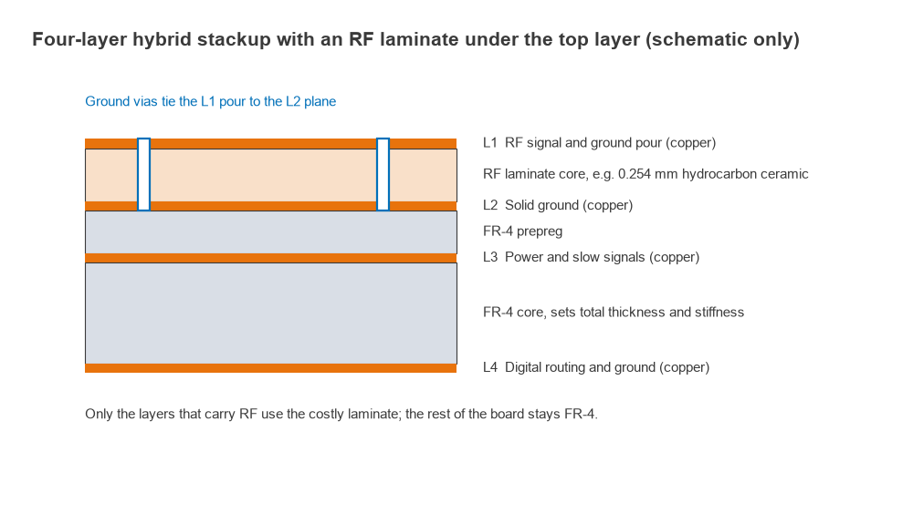
Hybrids need care in a few areas:
- Different materials expand at different rates with temperature, which can warp a board or stress vias if the stackup is not balanced.
- The lamination cycle and bonding prepreg must suit both materials; the fabricator usually decides this.
- Drilling and hole cleaning parameters differ between materials, especially when PTFE is involved.
- Ground vias on the RF layer must still reach the plane directly below it; see grounding and via stitching.
Cost Considerations
RF laminates cost considerably more per panel than FR-4, and PTFE materials more again; lead times and minimum order quantities can also be longer. Prices vary with region, volume and grade, so the only reliable figure is a quote from the fabricator for the actual stackup. A hybrid stackup typically recovers much of the difference, since only one or two thin RF layers use the expensive material. Before committing, compare the extra laminate cost with the cost of the alternative: more gain stages to cover line loss, tunable or trimmed filters, or yield lost to Dk variation.
Frequently asked questions
Can you use FR-4 for RF?
Yes, for most designs below a few gigahertz with short RF lines and bought-in filters. A 50 Ω line on FR-4 loses roughly 0.1 dB per centimetre at 2.4 GHz in the worked example above, which is acceptable for short feeds. Printed filters, long lines and millimetre-wave circuits are where FR-4 falls short.
When do you need Rogers material?
When loss, phase accuracy or repeatability set the performance: printed filters and couplers, antenna arrays, long feed lines, and most designs above roughly 10 GHz. A hybrid stackup lets the RF layer use the better laminate while the rest of the board stays FR-4.
Which Dk value should I use for impedance calculations?
Use the design Dk at the operating frequency, from the laminate datasheet or the fabricator’s stackup report, not a 1 MHz figure. For FR-4, ask the fabricator for the Dk of the specific prepreg and core they will use, since values vary with resin content.
Related topics
Trace widths for any laminate can be calculated with the microstrip calculator, and the alternatives to microstrip are compared in coplanar waveguide and stripline. Loss mechanisms are covered in transmission line losses. Other pages in this section deal with shielding and power supply decoupling, and the full topic map is on the RF design pillar page.