

An RF shield can is a soldered metal enclosure placed over part of a circuit board to stop radiated coupling into or out of that circuit. A board needs one when the isolation required between an aggressor and a victim circuit exceeds what layout, grounding and filtering alone can deliver, or when a regulatory or coexistence test fails on radiated emissions or desense.
This page is part of the RF PCB layout section of the RF design guide. It explains how to set an isolation target, how a can actually blocks energy, why an enclosed can behaves as a resonant cavity, how absorbers damp those resonances, and how to lay out a can footprint step by step.
Do you need a shield can?
A can is the last of several isolation tools, not the first. Placement, a continuous ground plane, via stitching and ground fences, and supply decoupling remove most coupling paths at no cost. A can adds price, height, assembly steps and rework difficulty, so it should answer a specific number: the isolation target. The usual reasons a design needs one are:
- A transmitter and a sensitive receiver share the board and must operate at the same time.
- An oscillator, synthesizer or clock has a fundamental or harmonic inside a receive band.
- A power amplifier output could couple back to its own input or to the VCO, causing oscillation or pulling.
- Radiated emission or immunity tests fail, as discussed under EMC and EMI.
- A pre-certified radio module is being designed and must behave the same in any host product.
Setting an isolation target
The required isolation between two circuits is the difference between what the aggressor produces at the victim frequency and what the victim can tolerate:
Isolation (dB) = Paggressor (dBm, at the victim frequency) − Pallowed (dBm)
For a receiver, the allowed level is set relative to its noise floor, N = −174 dBm/Hz + 10·log10(B) + NF, using the kTB density at room temperature. Noise-like interference that sits X dB below the floor raises it by 10·log10(1 + 10−X/10) dB. A common design choice is X = 6 dB, which costs just under 1 dB of sensitivity.
Worked example: two aggressors, one receiver
A receiver has a 1 MHz channel and a 3 dB noise figure. Its floor is −174 + 60 + 3 = −111 dBm. Allowing interference 6 dB below that gives Pallowed = −117 dBm and a desense of 0.97 dB.
- Transmitter noise. A co-located transmitter has an output noise density of −130 dBm/Hz at the receive frequency. In 1 MHz that is −130 + 60 = −70 dBm, so the path from transmitter to receiver needs −70 − (−117) = 47 dB of isolation.
- Oscillator spur. An on-board oscillator at 0 dBm has a harmonic that falls in the receive channel at, say, −20 dBm. The path then needs −20 − (−117) = 97 dB. If the fundamental itself lands in the channel at 0 dBm, the figure becomes 117 dB.
The first target is usually reachable with layout and filtering alone. The second is not: as an approximate planning figure, well separated sections on a board with a solid ground achieve isolation in the range of a few tens of dB, and a well-made can with compartments adds a few tens of dB more. Numbers like 97 dB and 117 dB also depend on conducted paths through supplies and control lines, which is why the can, the decoupling and the routing are designed together. The same arithmetic appears in receiver blocking and desense and in multi-radio coexistence planning.
How a shield can blocks energy
A solid metal wall stops RF in two ways: reflection at the surface, because the wall impedance is far below that of the incident wave, and absorption as the field decays through the metal thickness t. Absorption loss is
A = 8.686 · t / δ dB, with skin depth δ = 1 / √(π f μ σ)
Taking a copper-nickel-zinc (nickel silver) can alloy with an approximate conductivity of 3.5 × 10⁶ S/m and a wall 0.15 mm thick, the skin depth is 8.5 µm at 1 GHz and absorption alone is about 153 dB. At 100 MHz it is still about 48 dB. Above a few hundred megahertz, then, the metal itself is not the limit. Energy gets in and out through the openings: seams between wall and lid, gaps in the solder joint to the board, ventilation or tuning holes, and every trace that crosses under the wall.
Apertures and seams
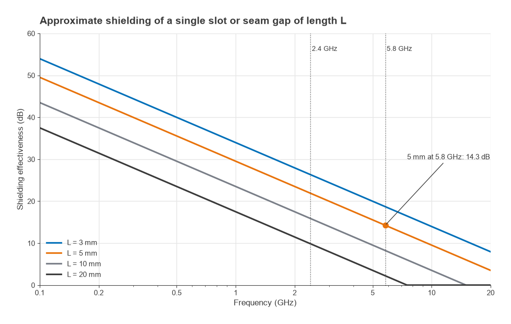
A slot behaves as a slot antenna. A widely used approximation for the shielding effectiveness of a single slot of longest dimension L, valid while L is less than half a wavelength, is
SE ≈ 20·log10(λ / 2L) dB
and n similar apertures close together reduce it by roughly 10·log10(n) dB. A 5 mm gap gives about 21.9 dB at 2.4 GHz but only 14.3 dB at 5.8 GHz, where λ is 51.7 mm. Ten such gaps along a lid seam remove another 10 dB. What matters is the longest dimension, not the area: a thin 10 mm slot leaks more than a round 3 mm hole. This is why lid spring fingers, solder fillets along the wall and the via spacing under the wall all need to stay well below λ/20 at the highest frequency of concern.
Cavity resonance inside the can
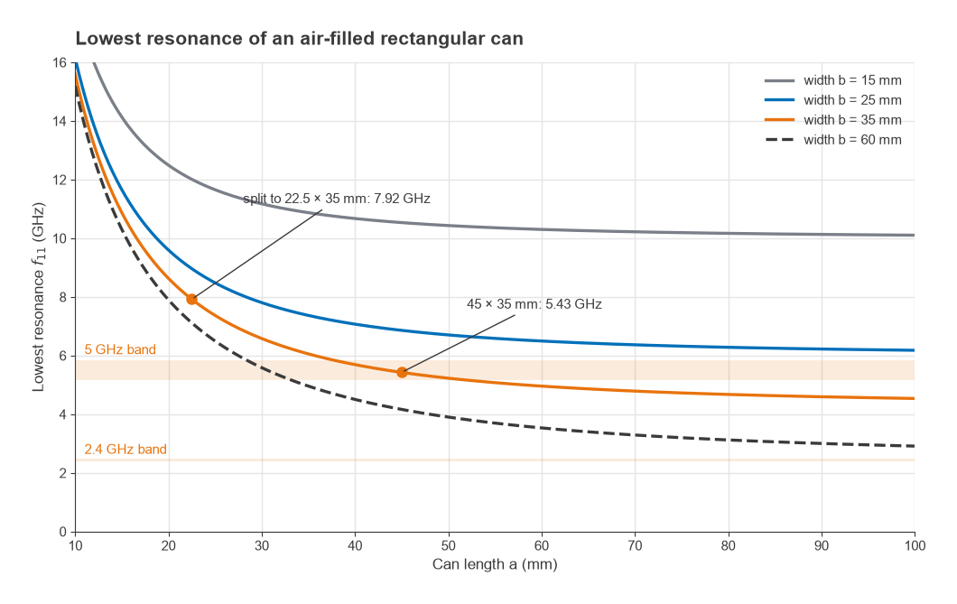
A closed can sitting on a ground plane is a rectangular cavity. When the can height h is smaller than its length a and width b, the lowest resonant mode has its electric field vertical, between lid and ground, and its frequency is
fmn = (c / 2) · √((m/a)2 + (n/b)2), lowest mode m = n = 1
for an air-filled can. The board dielectric under the can loads the cavity slightly and pulls the real resonance a little lower. At resonance, fields from one circuit build up across the whole cavity and couple strongly into everything else inside it. A can whose first resonance falls in an operating band can make isolation worse than no can at all.
Worked example: a dual-band module can
A 2.4/5 GHz radio is covered by one 45 × 35 mm can. The lowest mode is
f11 = (2.998 × 10⁸ / 2) · √((1/0.045)2 + (1/0.035)2) = 5.43 GHz
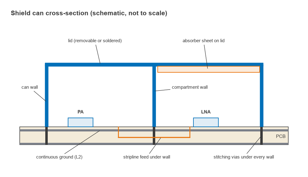
which falls inside the 5.15 to 5.85 GHz band. The next modes are at 7.92 GHz and 9.19 GHz. Adding a compartment wall across the long dimension creates two 22.5 × 35 mm cavities, each with a lowest mode of 7.92 GHz, clear of both bands. The wall also separates the transmit and receive sections, so one change fixes two problems.
| Can footprint (mm) | Lowest mode f11 | Comment |
|---|---|---|
| 30 × 20 | 9.01 GHz | Clear of sub-6 GHz bands |
| 45 × 35 | 5.43 GHz | Inside the 5 GHz Wi-Fi band |
| 22.5 × 35 | 7.92 GHz | 45 × 35 split in two |
| 50 × 40 | 4.80 GHz | Harmonics of 2.4 GHz nearby |
| 80 × 60 | 3.12 GHz | Large cans resonate low |
The rule that follows is simple: keep each compartment small enough that its lowest mode sits above the highest frequency of concern, including significant harmonics. A first check with the formula takes seconds; a full-wave EM simulation of the can with the board stack-up included gives the loaded frequencies and the coupling between specific components.
Absorbers and cavity damping
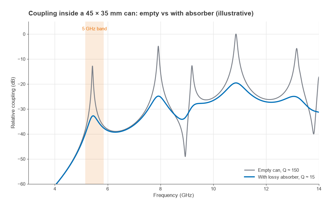
When a can cannot be partitioned, its resonances can be damped. Lossy absorber sheets, typically ferrite or carbon-loaded elastomer, are bonded to the inside of the lid. They lower the cavity Q, and because coupling at a resonance peak scales with Q, the peak reduction is approximately
ΔC ≈ 20·log10(Qempty / Qloaded) dB
Taking illustrative values, an empty can with Q ≈ 150 loaded down to Q ≈ 15 lowers the resonant coupling peak by 20 dB. Away from resonance the absorber changes little, because the coupling there is not controlled by stored energy. Absorbers work best where the magnetic field is strong, which for the lowest mode is near the walls, and they must be chosen for the frequency range in question, since their loss varies widely with frequency. They also sit close to circuits under the lid and can detune nearby matching networks or resonators, so tune the circuit with the absorber fitted.
How to lay out a shield can: step by step
- Set the isolation target for each aggressor and victim pair using the floor and allowance arithmetic above.
- Group circuits into compartments: transmit, receive, synthesizer, and digital or power circuits each in their own space where the target demands it.
- Check each compartment’s lowest resonance with f11 and resize or add walls until it clears the bands and their harmonics.
- Draw a continuous wall pad on the top layer with a solid ground on the next layer, and stitch it with vias at λ/20 or tighter in the board dielectric.
- Route signals out under the wall as stripline on an inner layer, never through a notch in the wall pad, which would act as an aperture. Filter supply and control lines where they leave the compartment.
- Keep openings short: limit lid finger pitch, tooling holes and any wall cut-outs to well under λ/20 at the highest frequency of concern.
- Leave clearance of at least a millimetre or so between tall components and the lid, and keep matching networks away from the lid if absorber will be fitted.
- Plan for debug: a two-piece can (fence plus clip-on lid) allows tuning and rework; a one-piece can is cheaper and usually seals better.
- Measure isolation and radiated emissions with and without the lid, using the methods in measuring radio performance, and add absorber only where a resonance shows up.
The stack-up under the can matters as much as the metal above it. A thin dielectric between the top layer and the first ground keeps fields contained and the via inductance low; the material trade-offs are covered in FR-4 vs Rogers.
Frequently asked questions
Do I need an RF shield can?
You need one when the isolation target between an aggressor and a victim exceeds what layout, grounding and filtering provide, or when emission or coexistence tests fail. Work out the target from the receiver floor and the aggressor level first. If it is below roughly 40 to 50 dB, careful layout often suffices; targets near 100 dB generally call for a can with compartments.
Why can a shield can make isolation worse?
A closed can is a resonant cavity. At its resonant frequencies the field builds up and couples every circuit inside it to every other. If the lowest mode falls in an operating band, coupling inside the can can exceed the coupling with no can at all. Splitting the can or adding absorber fixes this.
How far apart should the vias under a can wall be?
A common guideline is λ/20 or closer at the highest frequency of concern, using the wavelength in the board dielectric. In FR-4 that is around 3 mm at 2.4 GHz and a little over 1 mm at 5.8 GHz. Closer spacing also lowers the inductance between the wall and the ground plane.
What does an absorber sheet do inside a can?
It adds loss to the cavity, lowering its Q and therefore the height of the resonant coupling peaks. A drop in Q from 150 to 15 reduces a peak by about 20 dB. It does little away from resonance and can detune nearby circuits, so it is a targeted fix rather than a general one.
Related topics
Shielding works alongside grounding and via stitching, power supply decoupling and the system-level view in RF EMC and EMI and RF coexistence. All of these sit within the RF PCB layout hub, and terms used here are defined in the wireless terms glossary.