

Mixed-mode S-parameters are scattering parameters expressed in terms of differential and common-mode waves instead of single-ended waves. Sdd21, for example, is the differential transmission from logical port 1 to logical port 2: the differential output produced by a purely differential input. A four-port single-ended S-matrix converts exactly into a two-port mixed-mode matrix with differential, common-mode and mode-conversion terms.
Differential circuits are everywhere in RF and high-speed design: LNA and mixer inputs, ADC and DAC interfaces, baluns, differential antennas and multi-gigabit serial links. Single-ended S-parameters describe them completely but hide what matters, namely how well the wanted differential signal passes and how much of it leaks into common mode. This page, part of the S-parameters section of the RF design guide, defines the mixed-mode quantities, gives the conversion from a single-ended four-port, and works two numerical examples.
Differential and Common-Mode Waves
Group the four single-ended ports of a differential device into two logical ports. Each logical port has two conductors. A purely differential signal drives them with equal amplitude and opposite sign; a purely common-mode signal drives them with equal amplitude and the same sign. Any pair of incident waves a1 and a2 can be written as a combination of the two:
ad1 = (a1 − a2)/√2, ac1 = (a1 + a2)/√2
with the same definitions for the reflected waves b and for the second logical port. The factor 1/√2 keeps power consistent: the power carried by the differential and common-mode waves together equals the power in the two single-ended waves.
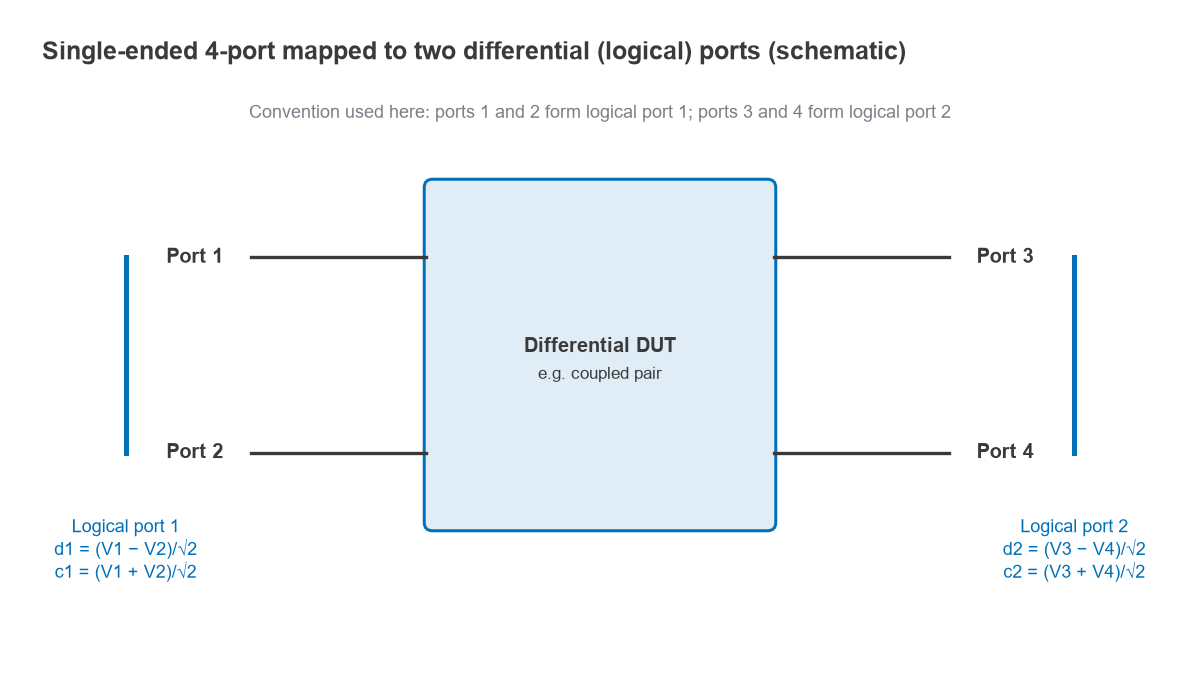
The mode reference impedances follow from this normalisation. If each single-ended port is referenced to Z0 = 50 Ω, the differential mode sees 2Z0 = 100 Ω and the common mode sees Z0/2 = 25 Ω. For a coupled pair with odd-mode impedance Zodd and even-mode impedance Zeven, the differential impedance is 2Zodd and the common-mode impedance is Zeven/2. An uncoupled pair of 50 Ω lines is therefore matched in both modes, while a tightly coupled 100 Ω differential pair has an even-mode impedance above 50 Ω and is not matched to 25 Ω in common mode.
Sdd, Scc, Sdc and Scd Definitions
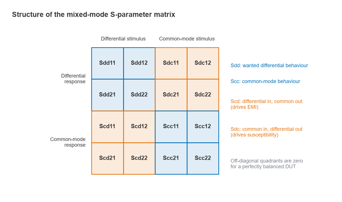
The mixed-mode matrix relates reflected mode waves to incident mode waves. It is written as four 2 × 2 blocks:
[bd; bc] = [[Sdd, Sdc], [Scd, Scc]] · [ad; ac]
- Sdd: differential stimulus, differential response. Sdd11 is differential return loss and Sdd21 differential insertion loss. This is the behaviour the designer intends.
- Scc: common-mode stimulus, common-mode response. Scc21 shows how freely common-mode noise passes through.
- Scd: differential stimulus, common-mode response. Scd21 measures how much of the wanted signal is converted to common mode, which radiates and causes EMI.
- Sdc: common-mode stimulus, differential response. Sdc21 measures how much common-mode noise is converted into the differential signal, which sets susceptibility.
The subscripts read as response then stimulus: in Scd21 the first letter (c) is the output mode and the second (d) the input mode, followed by output port then input port. A perfectly symmetric (balanced) device has zero mode-conversion blocks, so Sdc and Scd are direct measures of imbalance.
Conversion from a Single-Ended Four-Port
Port numbering must be fixed before any conversion. The convention used here groups single-ended ports 1 and 2 as logical port 1, and ports 3 and 4 as logical port 2. Many instruments and simulators use a different convention, pairing ports 1 and 3 on one side and 2 and 4 on the other, so the formulas must be adapted to the numbering in the file. Getting this wrong is the most common source of nonsense mixed-mode results from a Touchstone .s4p file.
With that grouping, define the transformation matrix
M = (1/√2) · [[1, −1, 0, 0], [0, 0, 1, −1], [1, 1, 0, 0], [0, 0, 1, 1]]
The rows give d1, d2, c1 and c2 in that order. Since M is orthogonal, M−1 = MT, and the mixed-mode matrix is
Smm = M · S · MT
Writing out the most used terms:
- Sdd11 = (S11 − S12 − S21 + S22)/2
- Sdd21 = (S31 − S32 − S41 + S42)/2
- Scc11 = (S11 + S12 + S21 + S22)/2
- Scc21 = (S31 + S32 + S41 + S42)/2
- Scd21 = (S31 − S32 + S41 − S42)/2
- Sdc21 = (S31 + S32 − S41 − S42)/2
These are linear combinations of complex S-parameters, so the conversion must be done on the complex values at each frequency, never on magnitudes in dB. Tools such as Python and scikit-rf include the conversion, but the port-grouping argument still has to match the file.
Worked example: converting a four-port matrix
Take a hypothetical, real-valued four-port matrix chosen to make the arithmetic easy to follow. Line A runs from port 1 to port 3 and line B from port 2 to port 4. S11 = S33 = 0.10, S22 = S44 = 0.12, S12 = 0.05, S34 = 0.05, S31 = 0.90, S42 = 0.85, and the cross-coupling terms are S41 = 0.08 and S32 = 0.06. The matrix is symmetric because the device is reciprocal.
- Sdd11 = (0.10 − 0.05 − 0.05 + 0.12)/2 = 0.06, a differential return loss of 24.4 dB.
- Sdd21 = (0.90 − 0.06 − 0.08 + 0.85)/2 = 0.805, or −1.88 dB.
- Scc21 = (0.90 + 0.06 + 0.08 + 0.85)/2 = 0.945, or −0.49 dB.
- Scd21 = (0.90 − 0.06 + 0.08 − 0.85)/2 = 0.035, or −29.1 dB.
- Sdc21 = (0.90 + 0.06 − 0.08 − 0.85)/2 = 0.015, or −36.5 dB.
The cross-coupling terms reduce differential transmission but help common-mode transmission, because they subtract in one case and add in the other. The mode conversion comes from asymmetry: the two lines have different transmission (0.90 against 0.85) and different coupling (0.08 against 0.06). If both lines and both coupling terms were identical, Scd21 and Sdc21 would be exactly zero. The full matrix computed with M · S · MT gives the same numbers, which is a useful check on any hand calculation.
Skew and Mode Conversion
Intra-pair skew is the commonest source of mode conversion on a board. Consider two uncoupled, perfectly matched 50 Ω lines with delays τ1 and τ2, so S31 = exp(−j2πfτ1) and S42 = exp(−j2πfτ2) with all other terms zero. The formulas reduce to Sdd21 = (S31 + S42)/2 and Scd21 = (S31 − S42)/2, whose magnitudes are
|Sdd21| = |cos(πfΔτ)|, |Scd21| = |sin(πfΔτ)|
where Δτ = τ2 − τ1. With 10 ps of skew at 10 GHz, πfΔτ = 0.1π, so |Sdd21| = cos 18° = 0.951 (−0.44 dB) and |Scd21| = sin 18° = 0.309 (−10.2 dB). The differential loss is small, but nearly a tenth of the signal power has become common mode. With 5 ps of skew, Scd21 at 10 GHz falls to −16.1 dB; with 20 ps it rises to −4.6 dB, and Sdd21 has a null at 1/(2Δτ) = 25 GHz where the two halves arrive exactly out of step.
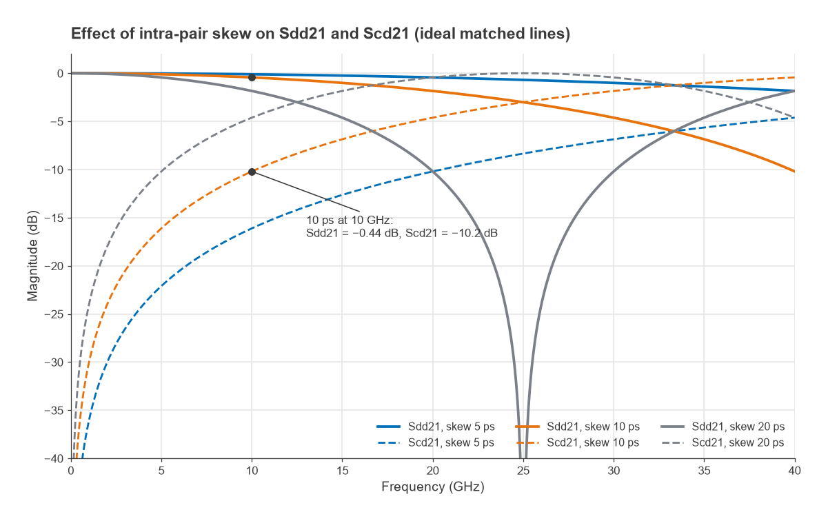
For scale, a stripline in a dielectric with εr of about 4 has a delay of roughly 6.7 ps per millimetre, so 10 ps corresponds to about 1.5 mm of length mismatch. Length matching of differential pairs, symmetric routing around bends and identical via structures on both lines are the layout measures that keep Scd21 down. The EMI consequences of common-mode current are covered in EMC and EMI for RF designers.
Measuring Mixed-Mode S-Parameters
A four-port vector network analyser measures the single-ended matrix one port at a time and computes the mixed-mode terms with the transformation above. For a linear device this is exact. Some analysers can also drive two ports simultaneously with true differential or common-mode stimulus, which matters for devices whose behaviour depends on the drive, such as limiting amplifiers or active circuits near compression. In both cases a full four-port calibration is needed, and fixture effects are removed with de-embedding before conversion, since de-embedding acts on the single-ended matrix.
Differential amplifier gain and stability can be assessed from the Sdd block in the same way as single-ended two-ports, using the definitions in RF power gain definitions and stability and the K-factor, provided the common-mode behaviour is also checked for oscillation. A balun measured as a three-port is analysed with the same idea, grouping its two balanced ports into one differential port.
Frequently Asked Questions
What are differential S-parameters (Sdd21)?
They are S-parameters for differential waves. Sdd21 is the differential output at logical port 2 divided by the differential input at logical port 1, with both ports terminated in their differential reference impedance, usually 100 Ω. It is the differential equivalent of S21.
What does Scd21 tell me?
Scd21 is the common-mode output produced by a differential input. A large value means the structure is unbalanced, usually through skew or asymmetric coupling, and that part of the signal will appear as common-mode current that can radiate.
Why is the differential reference impedance 100 Ω?
When each single-ended port is 50 Ω, the differential wave sees the two ports in series, 2 × 50 = 100 Ω, and the common-mode wave sees them in parallel, 25 Ω. Other reference impedances can be used by renormalising the single-ended matrix first.
Can I convert dB magnitudes from an .s4p file directly?
No. The conversion adds and subtracts complex S-parameters, so phase is essential. Convert the complex data at each frequency, then take magnitudes.
Related Topics
The S-parameters hub introduces the single-ended definitions this page builds on. Differential lines themselves are covered under stripline and coplanar waveguide, and differential receiver front ends appear in Radio Architectures Part 12: zero-IF receivers.