

Receiver desensitization, or desense, is a loss of sensitivity caused by a strong unwanted signal outside the wanted channel, so that a weak wanted signal that would otherwise be received is no longer detected. It is caused mainly by three mechanisms: gain compression by the blocker, reciprocal mixing of the blocker with local oscillator phase noise, and noise or carrier leakage from a co-located transmitter.
Sensitivity is normally specified with nothing else on the air. Real receivers share the spectrum with nearby transmitters, adjacent channels and their own transmit path. A blocking specification asks a harder question: how strong can an interferer at a given offset be before the receiver’s sensitivity degrades by a stated amount? This page explains each desense mechanism, gives the formulas to estimate it, and works through numeric examples. It belongs to the RF linearity section of the RF design reference.
Measuring desense
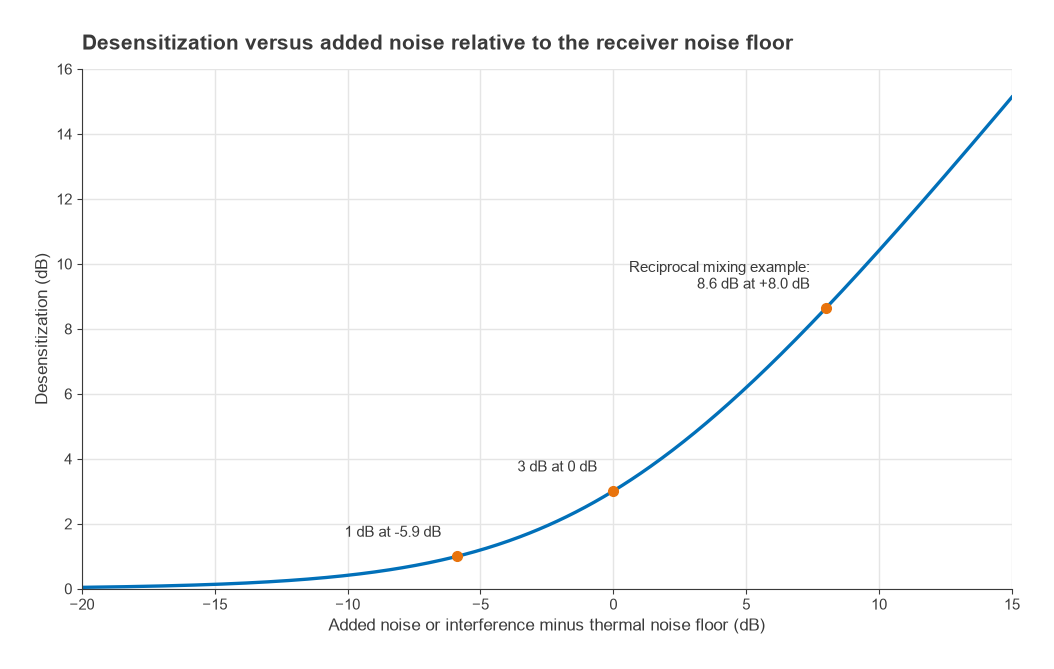
All desense mechanisms reduce the signal-to-noise ratio at the detector, either by lowering the wanted signal or by raising the noise and interference floor. If an interference or noise power Nadd joins the receiver’s own noise floor N0, the sensitivity degrades by
Desense (dB) = 10log10(1 + Nadd/N0)
Added noise equal to the floor costs 3 dB. Added noise 5.9 dB below the floor costs 1 dB, a common design target. Added noise 8 dB above the floor costs 8.6 dB. Figure 1 plots the full curve. The same expression applies whether the added power comes from phase noise, transmitter leakage or intermodulation, which makes it the common currency for budgeting desense. The thermal floor itself comes from kTB and the receiver noise figure, as described on the receiver sensitivity page.
Compression by blockers
A strong signal drives the LNA, mixer or ADC into its nonlinear region. With the third-order power-series model y = a1x + a2x2 + a3x3, a weak wanted signal in the presence of a blocker of amplitude Ab sees a gain of
Gwanted = a1 + (3/2)a3Ab2
The factor 3/2 is twice the 3/4 that governs a single tone compressing itself, so a blocker is more effective at compressing a weak neighbour than at compressing itself. Writing the amplitude in terms of the input third-order intercept point gives a convenient form:
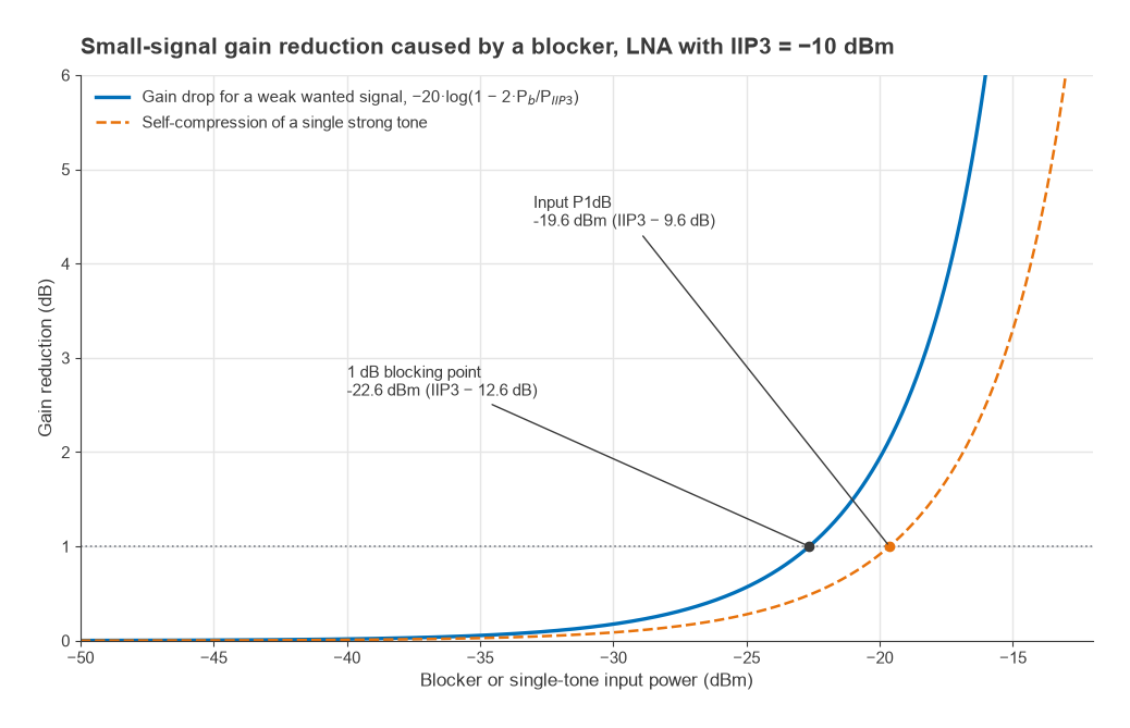
Gain reduction (dB) = −20log10(1 − 2Pb/PIIP3), with powers in linear units
Setting the reduction to 1 dB gives Pb = IIP3 − 12.6 dB. Since the single-tone input 1 dB compression point in the same model is IIP3 − 9.6 dB, the 1 dB blocking point sits about 3 dB below P1dB. For an LNA with IIP3 = −10 dBm, the 1 dB blocking point is −22.6 dBm, while the input P1dB is −19.6 dBm. A blocker at −30 dBm reduces gain by only 0.18 dB; at −20 dBm the reduction is 1.94 dB, and it rises steeply from there.
Lost gain in the first stage matters only to the extent that it raises the cascaded noise figure or pushes the wanted signal toward the noise of later stages, so a 1 dB gain drop in the LNA often costs less than 1 dB of sensitivity. In practice, though, compression rarely stops at the gain change. The same blocker drives the stage further into nonlinearity, its bias point shifts, and later stages such as the mixer and ADC may clip first. The model is a useful bound, not a complete prediction. Intermodulation between two blockers is a separate mechanism, treated on its own page, and the cascaded IP3 page shows how linearity limits combine through a lineup.
Reciprocal mixing via LO phase noise
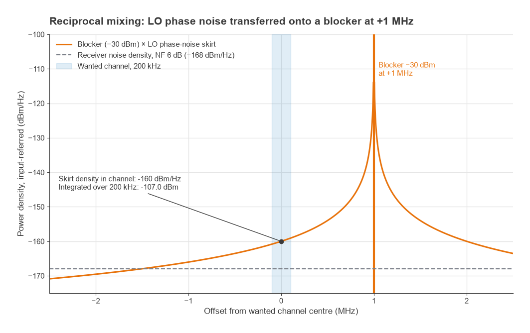
A mixer multiplies the incoming spectrum by the local oscillator. A real LO is not a pure tone; its phase noise forms skirts on either side of the carrier. A strong blocker at offset Δf from the wanted channel mixes with the LO’s phase-noise skirt at that same offset, and the product lands on top of the wanted signal at the IF. In effect, the blocker acquires a copy of the LO’s noise skirt, and the part of that skirt that falls in the wanted channel is noise the receiver cannot filter out.
The input-referred noise from reciprocal mixing is
NRM (dBm) = Pb (dBm) + L(Δf) (dBc/Hz) + 10log10(BW)
where L(Δf) is the LO phase noise at the blocker offset and BW is the channel noise bandwidth. Unlike compression, reciprocal mixing depends on the LO, not on the linearity of the RF stages. A perfectly linear front end still suffers it.
Worked example: blocker at 1 MHz offset
A receiver has a 200 kHz channel, 6 dB noise figure, and an LO with phase noise of −130 dBc/Hz at 1 MHz offset. A blocker of −30 dBm sits 1 MHz away.
- Bandwidth term: 10log(200 × 103) = 53.0 dB.
- Thermal floor: −174 + 53.0 + 6 = −115.0 dBm.
- Reciprocal mixing noise: −30 − 130 + 53.0 = −107.0 dBm, 8.0 dB above the thermal floor.
- Desense: 10log(1 + 100.8) = 8.6 dB. If the receiver needs 8 dB SNR, its sensitivity moves from −107.0 dBm to −98.4 dBm.
To hold desense to 1 dB, the reciprocal mixing noise must stay 5.9 dB below the floor, at −120.9 dBm. That requires L(1 MHz) ≤ −120.9 + 30 − 53.0 = −143.9 dBc/Hz, about 14 dB better than the LO in the example. Requirements like this, rather than in-channel noise, often set the phase noise specification of a synthesizer. The PLL frequency synthesis page describes how loop bandwidth and VCO choice shape the phase-noise profile at different offsets.
Co-located transmitter desense
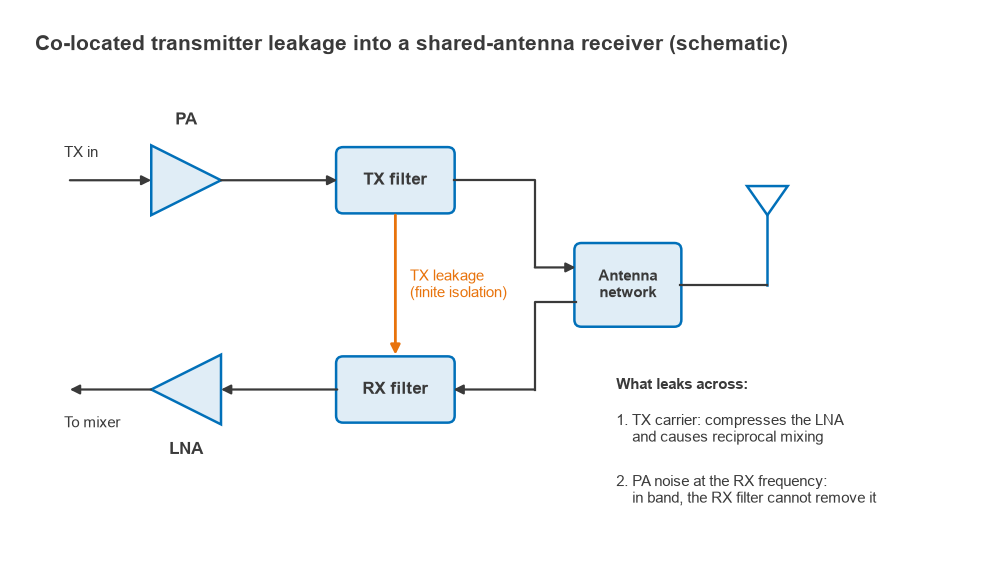
A transceiver that transmits and receives at the same time, such as a frequency-division duplex radio, or a device with several radios in one enclosure, faces its own transmitter as the worst blocker. Two separate problems arise, and they need different fixes.
The transmit carrier as a blocker
The transmit carrier reaches the LNA attenuated by the isolation of the duplexer or by the antenna-to-antenna coupling. With +30 dBm at the antenna port and 50 dB of transmit-band isolation, the carrier arrives at −20 dBm. For the LNA above, with IIP3 = −10 dBm, that is beyond the 1 dB blocking point and reduces gain by 1.94 dB. It also mixes with LO phase noise at the duplex offset, and with any second-order nonlinearity it can produce a baseband product in a zero-IF receiver. The fix is more isolation in the transmit band, a more linear LNA, or a cleaner LO. The duplexer vs diplexer page discusses how that isolation is obtained.
Transmitter noise in the receive band
The power amplifier also produces broadband noise, including at the receive frequency. That noise is in the receive band, so the receive filter passes it like a wanted signal. Only isolation between the transmitter output and the receiver input, measured at the receive frequency, can reduce it, which in a duplexer means rejection by the transmit filter in the receive band.
Suppose the PA output noise density at the receive frequency is −130 dBm/Hz and the receiver has a 3 dB noise figure, giving an input noise density of −174 + 3 = −171 dBm/Hz. For 1 dB of desense the leaked noise must be at or below −171 − 5.9 = −176.9 dBm/Hz, so the receive-band isolation must be at least −130 − (−176.9) = 46.9 dB. With 40 dB of isolation the desense is 3.5 dB; with 45 dB, 1.5 dB; with 50 dB, 0.5 dB; with 55 dB, 0.2 dB. Because this noise cannot be filtered at the receiver, the transmitter design must keep it low, typically with filtering between the PA driver and the PA as well as at the output.
Multi-radio products face the same arithmetic across different bands, for example a cellular transmitter next to a GNSS or Wi-Fi receiver. Antenna placement, shielding and filtering are the tools there, covered on the RF coexistence page.
Budgeting for blockers
A receiver design normally sets a desense allowance, for example 1 to 3 dB for the specified blocking test, and splits it between mechanisms. Each contribution is converted to an equivalent added noise and summed in linear units before applying the desense formula. Close-in blockers usually stress reciprocal mixing and the selectivity of channel filters. Far-out blockers, attenuated less by narrow filters near the antenna, stress the compression point of the LNA and mixer. Preselection filtering before the LNA helps both, at the cost of noise figure. These trade-offs connect directly to spurious-free dynamic range, which describes the span between the noise floor and the level at which distortion appears.
Wireless standards usually specify blocking as a test: the receiver must still meet a stated, slightly relaxed sensitivity while an interferer of a given level sits at a given offset. The levels and offsets differ widely between systems, so the test definitions in the relevant standard are the starting point for any budget.
Frequently asked questions
What causes receiver desense?
A strong unwanted signal, through three main mechanisms: it compresses the LNA or mixer and reduces gain for the wanted signal; it mixes with the LO’s phase noise and spreads noise into the wanted channel; or, when it is the radio’s own transmitter, it brings broadband noise directly into the receive band. Each one lowers the signal-to-noise ratio at the detector.
What is the difference between blocking and intermodulation?
Blocking involves a single strong interferer that degrades reception through compression or reciprocal mixing. Intermodulation involves two or more interferers whose third-order products fall on the wanted channel. Blocking tests use one interferer; intermodulation tests use two, spaced so that their products land in the channel.
How much desense is acceptable?
It depends on the system and the specification. Many designs aim for about 1 dB from any single mechanism in normal operation, which requires the added noise to stay about 6 dB below the receiver’s own floor. Formal blocking tests often allow a few dB of degradation from the reference sensitivity.
Why does a better LNA not fix reciprocal mixing?
Reciprocal mixing arises in the mixer from the LO’s phase noise, and it scales with the blocker level at the mixer input. A more linear LNA does not change either quantity. Only a cleaner LO, or filtering that reduces the blocker before the mixer, reduces it.
Related topics
The linearity background for this page is in P1dB compression, intermodulation and intercept points and cascaded IP3. Receiver architecture choices that change blocking behaviour are covered in Radio Architectures Part 2: receivers, LOs and mixers. For definitions of the terms used here, see the wireless terms glossary.