

RF coexistence is the discipline of making several radios in one product work at the same time, so that one radio’s transmissions do not desensitize another’s receiver. Wi-Fi interferes with LTE or GNSS through four routes: its carrier blocks a nearby receiver, its wideband transmitter noise lands in the victim’s channel, its harmonics fall on other bands, and it mixes with other signals in nonlinear parts to create intermodulation products at the victim frequency.
A phone, a vehicle telematics unit or an industrial gateway can carry cellular, Wi-Fi, Bluetooth, GNSS and sometimes UWB or satellite radios a few centimetres apart. Each works on its own. Put together, they can lose tens of decibels of sensitivity unless the frequency plan, filtering, isolation and timing are designed as one system. This page belongs to the RF PCB layout section of the RF design guide and shows how to analyse harmonics and intermodulation and how to build an isolation budget.
Desense: The Quantity Being Protected
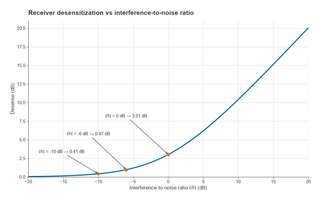
A victim receiver has a noise density N0 = −174 dBm/Hz + NF at its input. Interference with density I adds to that noise, and the sensitivity loss, or desense, is
D = 10 log10(1 + 10(I/N)/10) dB
where I/N is the interference-to-noise ratio in decibels. Interference equal to the noise floor (I/N = 0 dB) costs 3.01 dB, as Figure 1 shows. Holding desense to 1 dB requires I/N ≤ −5.9 dB, and I/N = −10 dB costs 0.41 dB. Many coexistence specifications are written as a maximum desense, often in the 1 to 3 dB range, so this relation converts the specification into a maximum interference level. The related single-receiver problem is covered in receiver blocking and desense.
How Interference Gets In
Figure 2 shows the coupling paths. The first is antenna-to-antenna coupling, set by antenna spacing, orientation, polarization and the ground currents they share. In a handset, the isolation between antennas is often only 10 to 20 dB because the whole chassis is part of each antenna. The second is a shared nonlinear part, such as an antenna switch, a diplexer with a nonlinear component, or an LNA that sees both signals. The third is conducted noise on supply rails and ground, for example a PA’s supply current modulating a shared regulator. The fourth is radiation from PA outputs, traces and inductors directly into nearby circuits, which shielding and via stitching are meant to stop.
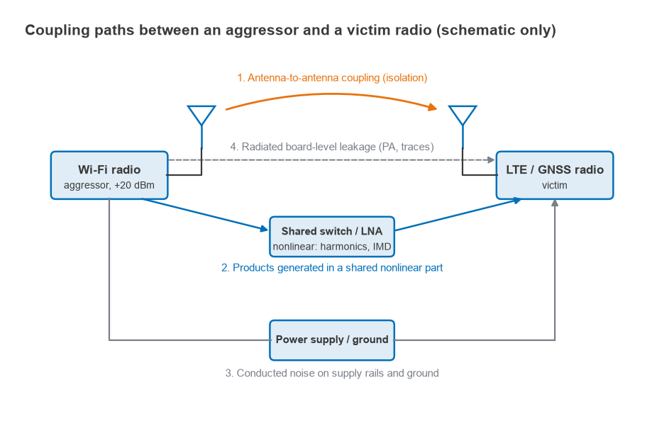
Through these paths the aggressor reaches the victim in three forms, and each needs a different remedy:
- Blocking. The aggressor carrier itself, out of the victim’s band, overloads the victim’s LNA or mixer. The remedy is filtering at the victim’s input and receiver linearity.
- Transmitter noise and spurious emissions. The aggressor’s PA puts out broadband noise and spurs that fall inside the victim’s channel. Nothing at the victim can remove them, so the remedy is filtering at the aggressor’s output and antenna isolation.
- Harmonics and intermodulation. Nonlinear parts create new frequencies that land on the victim. The remedy is a frequency plan that avoids them, filtering before any nonlinear part, and linearity where both signals meet.
Harmonic and IMD Analysis
The first coexistence task is arithmetic. For every pair of transmitters and every receiver in the product, list the harmonics nf1 and the low-order mixing products |mf1 ± nf2| across the full width of each band, and mark where they overlap a receive band. Second-order (IM2) products f1 ± f2 and third-order (IM3) products 2f1 − f2 are the usual offenders. The underlying distortion mechanisms are covered in harmonic distortion and intermodulation and intercept points, and the same method is used for mixer spurs in frequency planning.
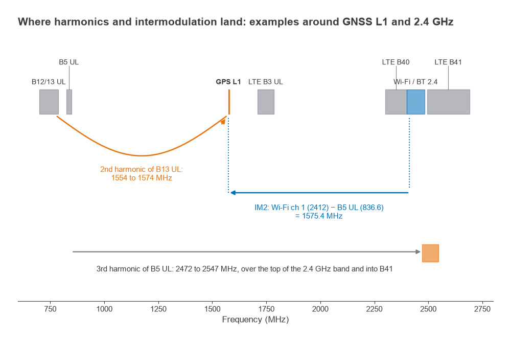
Figure 3 shows three well-known examples:
- LTE Band 13 second harmonic. The uplink at 777 to 787 MHz doubles to 1554 to 1574 MHz, immediately below GPS L1 at 1575.42 MHz and inside any practical GNSS filter.
- Wi-Fi and LTE Band 5 IM2. Wi-Fi channel 1 at 2412 MHz minus a Band 5 uplink at 836.6 MHz gives 1575.4 MHz, exactly on L1. With a 20 MHz Wi-Fi channel and a 10 MHz LTE carrier, the product spreads over about 30 MHz, so a range of channel combinations hits the GNSS band.
- LTE Band 5 third harmonic. 3 × (824 to 849 MHz) covers 2472 to 2547 MHz, which overlaps the top of the 2.4 GHz ISM band and the bottom of LTE Band 41.
Worked example: IM2 in a GNSS LNA
The input-referred level of an IM2 product is PIM2 = P1 + P2 − IIP2, all in dBm. Suppose the GNSS LNA input sees an LTE Band 5 signal at −10 dBm and Wi-Fi at −15 dBm through poor antenna isolation and no pre-filter, and the LNA has IIP2 = +20 dBm.
- PIM2 = −10 − 15 − 20 = −45 dBm
- Spread over about 30 MHz: −45 − 10 log10(3 × 10⁷) = −119.8 dBm/Hz
- GNSS noise density with NF = 1.2 dB: −172.8 dBm/Hz, so I/N = +53 dB and desense is about 53 dB
The GNSS receiver is effectively blind. Now add a pre-filter giving 40 dB of rejection at both 836 MHz and 2412 MHz. Each input falls by 40 dB, so the IM2 product falls by 80 dB, to −125 dBm, or −199.8 dBm/Hz. I/N is −27 dB and the desense is 0.009 dB. Because a second-order product drops 2 dB for every 1 dB of rejection applied to both inputs (3 dB for third order), filtering ahead of the first nonlinear part is by far the most effective fix. Improving IIP2 by 30 dB, to +50 dBm, would still leave 23 dB of desense in this example. The GNSS front-end design page covers the pre-filter trade-off in noise figure.
Building an Isolation Budget
An isolation budget works backward from the victim’s allowed desense to the isolation needed between aggressor and victim, then splits that isolation between antennas, filters and layout. It is done separately for transmitter noise and for blocking, since they need filters in different places.
- Set the desense target and convert it to a maximum interference density: Imax = N0 + 10 log10(10D/10 − 1).
- Find the aggressor’s noise density at the victim frequency, at its antenna port, from data sheets or measurement.
- The required isolation for noise is the difference between the two.
- Subtract the antenna isolation you can realistically achieve. The remainder must come from filtering at the aggressor output.
- Repeat for blocking: the aggressor carrier minus antenna isolation, compared with the victim’s blocking tolerance, gives the rejection needed in the victim’s receive filter.
Worked example: Wi-Fi into LTE Band 41
A Wi-Fi transmitter at +20 dBm on channel 13 (2472 MHz) shares a product with an LTE Band 41 receiver at 2.5 GHz with a 5 dB noise figure. Assume the Wi-Fi output noise at the LTE channel is −120 dBm/Hz at the Wi-Fi antenna port, and that the antennas give 15 dB of isolation. The target is 1 dB of desense.
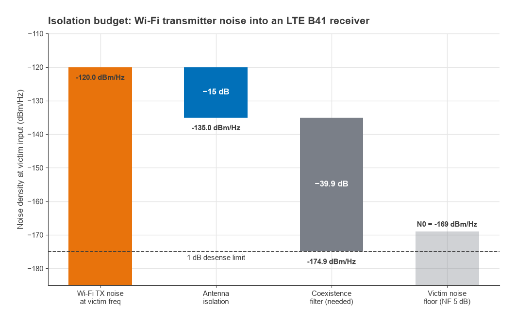
- N0 = −174 + 5 = −169 dBm/Hz
- I/N for 1 dB = 10 log10(100.1 − 1) = −5.9 dB, so Imax = −174.9 dBm/Hz
- Required isolation for noise = −120 − (−174.9) = 54.9 dB
- Filter rejection needed at the Wi-Fi output = 54.9 − 15 = 39.9 dB at the LTE frequency
- Blocking: the Wi-Fi carrier arrives at +20 − 15 = +5 dBm. If the LTE receiver tolerates −25 dBm at 2472 MHz, its receive filter needs 30 dB of rejection there
Figure 4 shows the noise budget as a waterfall. The difficulty is the frequency gap: only about 14 MHz separates the top edge of a 20 MHz channel 13 from the 2496 MHz start of Band 41, and achieving 40 dB across that gap needs a sharp acoustic filter. Coexistence filters of this kind, typically BAW, are described in SAW vs BAW filters. Where the filter cannot be sharp enough, the edge Wi-Fi channels are avoided or their power is reduced while LTE is receiving.
Design Techniques That Work
- Frequency planning. Run the harmonic and IMD analysis for every band combination the product supports, and let the software avoid the worst channel pairs.
- Antenna placement. Separate antennas as far as the enclosure allows, use orthogonal polarizations where possible, and place the GNSS antenna away from the main cellular antenna. Each extra decibel of antenna isolation reduces every filter requirement by a decibel.
- Filtering in the right place. Transmitter noise is filtered at the aggressor; blocking is filtered at the victim; intermodulation is filtered before the first nonlinear part. A duplexer or diplexer that shares one antenna between bands must be linear enough not to create products itself.
- Time-domain coordination. Wi-Fi and Bluetooth sharing the 2.4 GHz band, or Wi-Fi beside a TDD LTE band, are often coordinated by a packet traffic arbitration interface so they do not transmit while the other receives.
- Layout and power. Shield the PAs and the sensitive LNAs, give each radio its own filtered supply, and keep PA return currents away from receiver grounds, as in RF power supply decoupling.
- Verification. Measure desense in the complete product, conducted and radiated, with each aggressor at full power on its worst channel. Desense in a shielded chamber often differs from the bench because the enclosure changes the antenna isolation.
Antenna isolation in compact multi-antenna devices is discussed further in building smartphone antennas that play nice together and in RF front-end modules, Part 14 of Radio Architectures.
Frequently Asked Questions
Why does my Wi-Fi interfere with LTE or GNSS?
Because the radios are close together. The Wi-Fi carrier can block the other receiver, its transmitter noise can land in the victim channel, and it can mix with a cellular signal in a nonlinear part. Wi-Fi channel 1 minus LTE Band 5 at 836.6 MHz falls exactly on GPS L1.
How much isolation do two radios need?
Work backward from the allowed desense. In the Wi-Fi and Band 41 example, holding desense to 1 dB needs about 55 dB of isolation for transmitter noise, split as 15 dB from the antennas and 40 dB from filtering.
What is an acceptable desense?
It depends on the product and operator requirements, but limits in the range of 1 to 3 dB are common. One decibel corresponds to interference about 6 dB below the receiver noise floor.
Is filtering or linearity more effective against intermodulation?
Filtering before the nonlinear part, in most cases. A second-order product falls 2 dB for every decibel of rejection applied to both inputs, while each decibel of IIP2 improvement buys only 1 dB.
Related Topics
The RF PCB layout hub links the related layout topics, including RF EMC and EMI and FR-4 vs Rogers. Antenna isolation and placement connect to PCB antenna design, and the system view of several radios sharing one front end is in antennas and propagation in radio design, Part 17 of Radio Architectures.