

G/T, the ratio of antenna gain to system noise temperature, is the figure of merit of a satellite receiving station. Expressed in dB/K, it combines how much signal the antenna collects with how much noise the antenna and receiver add, so a single number predicts the carrier-to-noise density of the downlink once the satellite’s EIRP and the path loss are known.
Satellite communication RF design revolves around three quantities: EIRP on the transmit side, G/T on the receive side, and the path between them, including rain fade at higher bands. This page defines each one, assembles them into a satellite link budget, and works through a Ku-band geostationary downlink with and without rain. It is part of the RF design by application section of the RF design guide, and builds on the general RF link budget.
EIRP: Transmit Side
Effective isotropic radiated power is the power an isotropic antenna would need to produce the same power density in the direction of the receiver:
EIRP (dBW) = Pt (dBW) − Lfeed (dB) + Gt (dBi)
For a satellite, EIRP is usually published as a coverage contour map, with the highest value at beam centre and lower values toward the edge. For a ground terminal it is set by the block upconverter (BUC) output power, the loss between BUC and feed, and the dish gain. A reflector of diameter D and aperture efficiency η has gain
G = η (πD/λ)2
As an uplink example, a 4 W BUC (6.0 dBW) with 0.5 dB of feed loss driving a 1.2 m dish at 14 GHz with η = 0.65 gives G = 43.0 dBi and EIRP = 6.0 − 0.5 + 43.0 = 48.5 dBW. Aperture efficiency figures of 0.55 to 0.7 are typical for offset-fed dishes, and antenna gain is discussed further in antenna parameters. The BUC power amplifier must also meet spectral regrowth limits, which links uplink design to power amplifier classes and back-off.
G/T: Receive Figure of Merit
G/T is defined as
G/T (dB/K) = Gr (dBi) − 10 log10(Tsys)
where Gr and Tsys must be referred to the same point, usually the LNA input. The system noise temperature combines the antenna temperature Ta, the noise of any loss Lf between feed and LNA, and the LNA’s equivalent noise temperature:
Tsys = Ta/Lf + T0(1 − 1/Lf) + TLNA with TLNA = T0(F − 1)
Antenna temperature is low for a dish looking at clear sky at a reasonable elevation angle, often a few tens of kelvin including ground spillover, so the LNA and any loss ahead of it dominate. Every 0.1 dB of loss before the LNA adds about 6.6 K, which on an 80 K system is roughly 0.3 dB of G/T. This is why LNBs mount directly on the feed horn and why waveguide runs before the LNA are kept short. Noise temperature and noise figure are related in noise temperature and noise figure.
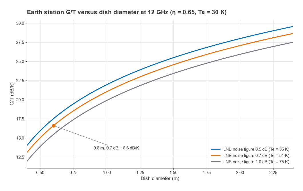
Worked example: G/T of a 0.6 m Ku-band terminal
- Wavelength at 12 GHz: λ = 0.025 m.
- Gain: G = 0.65 × (π × 0.6/0.025)2 = 3700, or 35.7 dBi.
- LNB noise figure 0.7 dB: TLNA = 290 × (100.07 − 1) = 50.7 K.
- Clear-sky antenna temperature, assumed: 30 K. The feed and LNB are integrated, so Lf ≈ 1.
- Tsys = 30 + 50.7 = 80.7 K, or 19.1 dBK.
- G/T = 35.7 − 19.1 = 16.6 dB/K.
The later stages of the LNB and the IF cable add very little because the LNB gain, typically 50 dB or more, divides their noise contribution, as the cascaded noise figure formula shows. Doubling the dish diameter adds 6 dB of G/T; improving the LNB from 1.0 dB to 0.5 dB noise figure adds about 2.1 dB at this antenna temperature.
The Satellite Link Budget
With EIRP and G/T defined, the carrier-to-noise density ratio of a link is
C/N0 (dBHz) = EIRP − Lfs − Latm − Lother + G/T − 10 log10k
where Lfs = 20 log10(4πd/λ) is the free-space path loss and 10 log10k = −228.6 dBW/K/Hz, so subtracting it adds 228.6 dB. The carrier-to-noise ratio in a noise bandwidth B and the energy per bit to noise density follow directly:
C/N = C/N0 − 10 log10B Eb/N0 = C/N0 − 10 log10Rb
The relationship between these ratios is explained in SNR and Eb/N0.
Worked example: Ku-band GEO downlink
Assume a geostationary satellite with 52 dBW EIRP toward the terminal, a slant range of 38,000 km (geostationary slant ranges run from about 35,800 km at the sub-satellite point to over 41,000 km near the coverage edge), 0.3 dB of clear-sky atmospheric loss, the 16.6 dB/K terminal above and a carrier at 27.5 Msymbol/s with a noise bandwidth taken equal to the symbol rate.
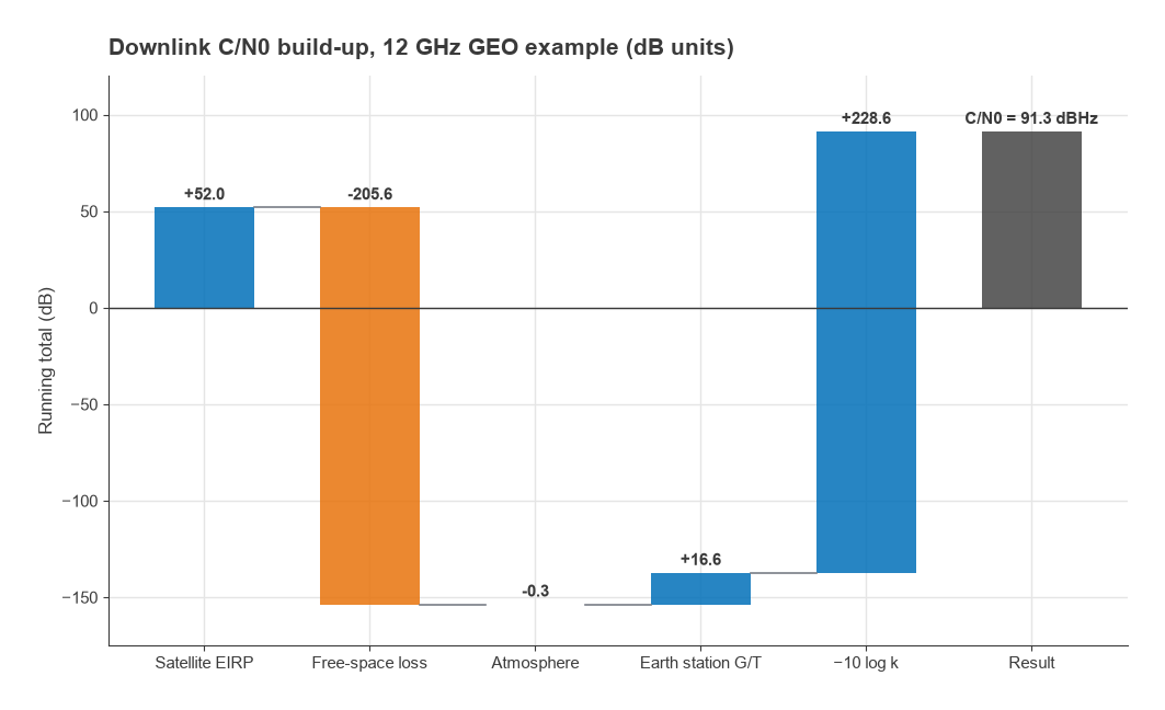
| Item | Value |
|---|---|
| Satellite EIRP | +52.0 dBW |
| Free-space loss, 38,000 km at 12 GHz | −205.6 dB |
| Atmospheric loss (clear sky) | −0.3 dB |
| Terminal G/T | +16.6 dB/K |
| −10 log10k | +228.6 dB |
| C/N0 | 91.3 dBHz |
| Noise bandwidth, 27.5 MHz | −74.4 dB |
| C/N, clear sky | 16.9 dB |
As a cross-check in absolute terms, the received carrier at the LNB input is 52 − 205.6 − 0.3 + 35.7 = −118.2 dBW, and the noise power kTsysB is −228.6 + 19.1 + 74.4 = −135.1 dBW, a difference of 16.9 dB. If the carrier uses QPSK with rate 3/4 coding, the information rate is about 41.3 Mb/s and Eb/N0 = 91.3 − 76.2 = 15.1 dB. Whether that is comfortable depends on the threshold of the chosen modulation and coding and on the margin needed for rain. A full link also adds the uplink and the satellite transponder’s own noise and intermodulation; the overall C/N is found by adding the noise-to-carrier ratios of each contribution in linear terms.
Rain Fade
Above about 10 GHz, rain is the largest variable loss on a satellite path. Raindrops absorb and scatter energy, with a specific attenuation that is commonly modelled as γ = kRα dB/km, where R is the rain rate in mm/h and k and α depend on frequency and polarisation. Values of k and α are tabulated in ITU-R recommendations; at Ku band, heavy rain of 25 mm/h gives roughly 1 dB/km, and the effect grows quickly at Ka band. The total attenuation is γ multiplied by an effective path length through the rain, which depends on elevation angle and on the height of the rain layer. System designers then size the margin for a fade depth that is exceeded only for a chosen small fraction of the year, using rain statistics for the terminal’s location. Antennas and propagation for radio design covers propagation effects more generally.
Rain hits the downlink twice
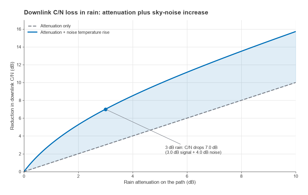
Rain that attenuates the signal by A dB also emits thermal noise, because an absorbing medium at physical temperature Tm radiates. The sky temperature seen by the antenna rises to
Ta,rain = Ta,clear × 10−A/10 + Tm(1 − 10−A/10)
with Tm commonly taken as about 270 to 290 K. In the worked example, 3 dB of rain with Tm = 275 K raises the antenna temperature from 30 K to 152.2 K and the system temperature from 80.7 K to 202.9 K, a 4.0 dB increase. The downlink C/N therefore falls by 3.0 dB of lost signal plus 4.0 dB of added noise, 7.0 dB in total, from 16.9 dB to 9.9 dB. The low-noise terminal suffers proportionally more, since rain noise is large compared with its small clear-sky Tsys. On the uplink the satellite antenna looks at the warm Earth, so rain changes its noise temperature very little and the uplink fade is close to the attenuation alone.
Countermeasures
The standard responses are a fixed margin in the link budget, uplink power control that raises the ground terminal’s output during a fade, adaptive coding and modulation that drops to a lower-order mode while the fade lasts, and, for large gateways, site diversity with a second station far enough away that heavy rain rarely covers both. Each of these trades capacity or cost against availability.
Ground Terminal RF Chain
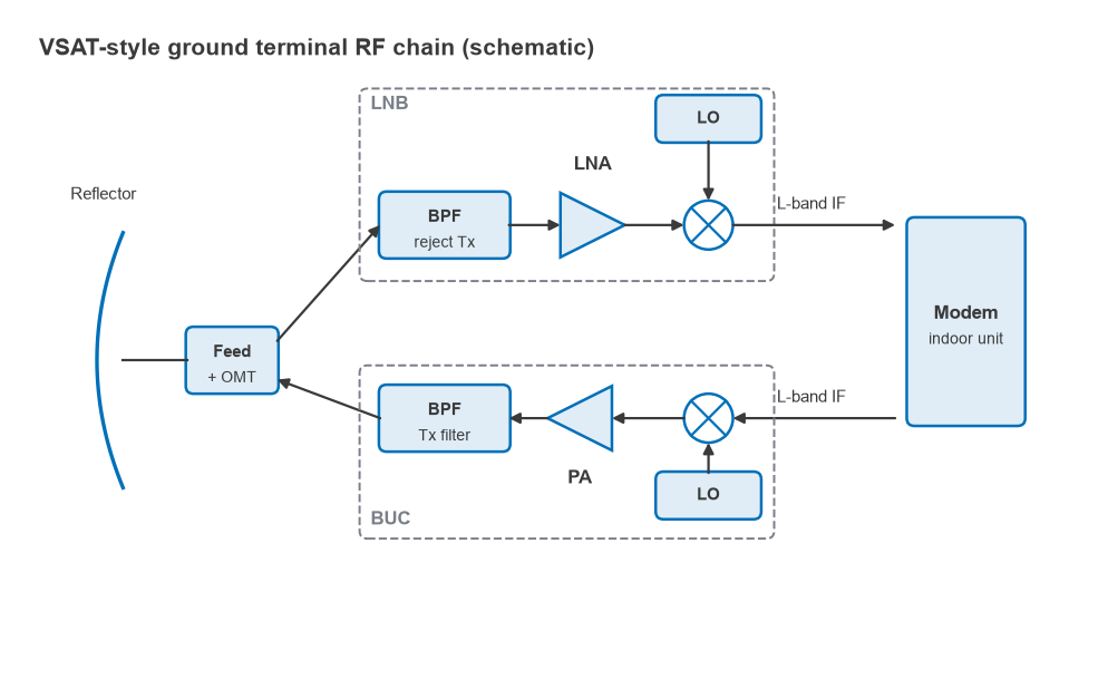
A typical VSAT or broadband terminal splits the RF hardware between an outdoor unit on the dish and an indoor modem. The feed horn and orthomode transducer separate transmit and receive polarisations. The receive path goes through a filter that rejects the terminal’s own transmit signal, a low-noise amplifier and a downconverter, packaged together as the LNB, and reaches the modem at L-band over coaxial cable. The transmit path runs the other way: the modem sends an L-band signal to the BUC, which upconverts and amplifies it. Isolation between the high-power transmit path and the sensitive receiver is set by the OMT, the transmit-reject filter and the frequency separation of the bands, a problem related to duplexer design.
Frequently Asked Questions
What is G/T?
G/T is the receive antenna gain divided by the system noise temperature, both referred to the same point, expressed in dB/K. It is the receive-side figure of merit in satellite links: C/N0 rises one-for-one with G/T. A 0.6 m Ku-band dish with a 0.7 dB LNB has a G/T of about 16.6 dB/K.
What is EIRP in satellite communication?
EIRP is transmitter power minus feed loss plus antenna gain, in dBW. For a satellite it describes the downlink power toward a given location; for a ground terminal it describes the uplink. A 4 W BUC on a 1.2 m dish at 14 GHz gives about 48.5 dBW.
How do you calculate a satellite link budget?
Add EIRP, subtract free-space and other path losses, add G/T and add 228.6 dB to get C/N0 in dBHz. Subtract 10 log10 of the noise bandwidth for C/N, or of the bit rate for Eb/N0, and compare with the demodulator threshold plus a rain margin.
Why is rain fade worse on the downlink?
On the downlink, rain both attenuates the signal and raises the sky noise temperature seen by a low-noise ground antenna. In the worked example 3 dB of rain costs 7.0 dB of C/N. The satellite receiver already sees a warm Earth, so on the uplink rain mainly costs the attenuation.
Related Topics
The RF design by application hub links other application areas, including LoRa network planning and software-defined radio. The link budget calculator handles the general terrestrial case, thermal noise and kTB explains the noise floor, and dB and dBm covers the units. Terms are defined in the wireless terms glossary.