

A GNSS front end is the low-noise receive chain between a satellite navigation antenna and the receiver IC, built to recover signals that arrive about 20 dB below the thermal noise floor. A GPS front end is designed by putting a low-noise amplifier as close to the antenna as possible, filtering with a SAW or similar band-pass filter, adding enough gain to overcome the cable, and protecting the first stage from strong nearby transmitters.
The noise figure decides the carrier-to-noise density the receiver sees in open sky. The filtering and linearity decide whether that performance survives next to a cellular modem or a jammer. This page works through both, using GPS L1 C/A at 1575.42 MHz as the example. It belongs to the RF design applications section of the RF design guide.
Why GNSS Front Ends Are Different
The minimum received power of the GPS L1 C/A signal at the Earth’s surface is about −130 dBm for a 0 dBi antenna. The thermal noise in the 2.046 MHz main-lobe bandwidth of the signal is
N = −174 dBm/Hz + 10 log10(2.046 × 10⁶) = −110.9 dBm
so the signal is about 19 dB below the noise before any processing. The receiver recovers it through the correlation gain of the spreading code, and its performance is expressed as carrier-to-noise density C/N0 in dB-Hz rather than as a signal-to-noise ratio in a bandwidth. Using the 290 K reference that defines noise figure,
C/N0 = Pr − (−174 dBm/Hz + NFsys)
Every decibel of system noise figure is a decibel of C/N0. A clear-sky antenna looks at a sky much colder than 290 K, so this expression is conservative; an exact budget uses the antenna noise temperature instead. Modern receivers typically acquire at somewhat above 30 dB-Hz and track down into the 20s, so a few decibels of front-end loss move the point at which a device loses lock under foliage, indoors or in an urban canyon.
Active Antenna Architecture
When the antenna is more than a few centimetres from the receiver, as on a vehicle roof, a timing receiver on a mast or a drone, it is built as an active antenna. A ceramic patch or helix feeds an LNA in the same housing, and the amplified signal travels down the coax. The receiver supplies DC on the centre conductor through a bias tee, typically 3.3 to 5 V at a few tens of milliamps, and the antenna separates it again with an RF choke and a DC block.
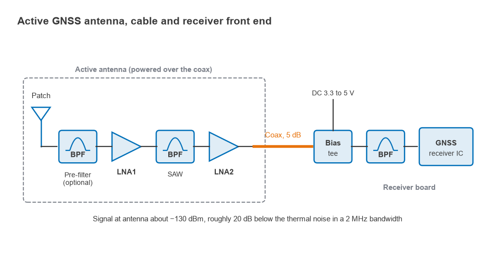
A typical active antenna contains two LNA stages with a band-pass filter between them, as in Figure 1. The first LNA sets the noise figure. The filter, usually a SAW for L1 alone or a wider ceramic or BAW filter for multi-band designs, removes out-of-band signals before they reach the second stage. The second LNA brings the total antenna gain up to the 25 to 35 dB range that is common, so that the cable and receiver add little noise. Too much gain is also a problem: a short cable to a receiver with its own LNA can overload the receiver input, which is why receiver data sheets usually state an allowed range of antenna gain minus cable loss.
LNA and SAW Cascade: Worked Example
The system noise figure follows from the Friis cascade formula, Fsys = F1 + (F2 − 1)/G1 + (F3 − 1)/(G1G2) + …, with passive parts having a noise figure equal to their loss. Take these stage values:
| Stage | Gain (dB) | NF (dB) |
|---|---|---|
| Antenna feed and match | −0.3 | 0.3 |
| LNA1 | 18 | 0.8 |
| SAW filter | −1.5 | 1.5 |
| LNA2 | 15 | 1.2 |
| Coax cable | −5 | 5 |
| Receiver IC | 20 | 3 |
The active antenna has 31.2 dB of gain. The cascaded noise figure is 1.16 dB, so with Pr = −130 dBm, C/N0 = −130 + 174 − 1.16 = 42.8 dB-Hz. Only 0.06 dB of the total comes from everything after the feed loss and LNA1’s own 0.8 dB, which is the point of the active design: the cable and receiver are hidden behind 31 dB of gain.
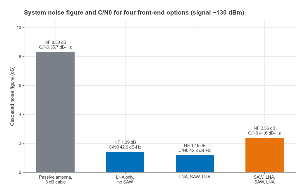
Figure 2 compares this with three alternatives. A passive antenna on the same 5 dB cable, straight into the receiver, gives 8.3 dB and 35.7 dB-Hz, a loss of 7 dB that would make indoor tracking marginal. A single LNA with no filter gives 1.39 dB, slightly worse because the cable now sits behind only 18 dB of gain. Adding a SAW pre-filter ahead of LNA1, with 1.2 dB of loss, raises the noise figure to 2.36 dB and costs 1.2 dB of C/N0. That trade is the central decision of GNSS front-end design.
Filtering and Jamming Resistance
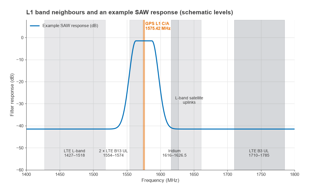
The spectrum around L1 is crowded, as Figure 3 shows. Mobile satellite uplinks, including Iridium at 1616 to 1626.5 MHz and other L-band services above it, sit within about 40 to 85 MHz. Mobile broadband allocations around 1427 to 1518 MHz lie below, and LTE Band 3 uplink at 1710 to 1785 MHz lies above. The second harmonic of LTE Band 13 uplink (777 to 787 MHz) falls at 1554 to 1574 MHz, directly beside L1 and inside the passband of any practical filter.
Blocking from co-located transmitters
In a phone, a tracker or a vehicle telematics unit, the GNSS antenna shares the product with cellular and Wi-Fi transmitters. Take a +23 dBm LTE Band 3 uplink and 10 dB of antenna-to-antenna isolation: +13 dBm arrives at the GNSS antenna port. That is far beyond the input compression point of a low-noise amplifier, which for a GNSS LNA is often in the range of −20 to −5 dBm. With a pre-filter giving about 40 dB of rejection at 1.71 GHz, the level at LNA1 falls to about −27 dBm, which a well-chosen LNA can tolerate. This is why handset and module designs often accept the 1 dB or so of C/N0 lost to a pre-filter, while roof-mounted antennas in a quieter environment put the LNA first. The mechanism is the same blocking and desensitization described in receiver blocking and desense, and the wider coexistence problem is treated in coexistence and desense in multi-radio products.
Filters cannot remove interference that lands in band, such as the Band 13 harmonic. That has to be stopped at the source, by harmonic filtering on the cellular transmitter, by layout and shielding, and by keeping nonlinear parts such as switches out of the GNSS path. Intermodulation is a related risk: two strong out-of-band signals can mix in the LNA and produce a product at L1, so the LNA’s intercept point matters as well as its compression point.
In-band jamming
An in-band jammer passes straight through every filter. Its effect on C/N0 is commonly estimated with
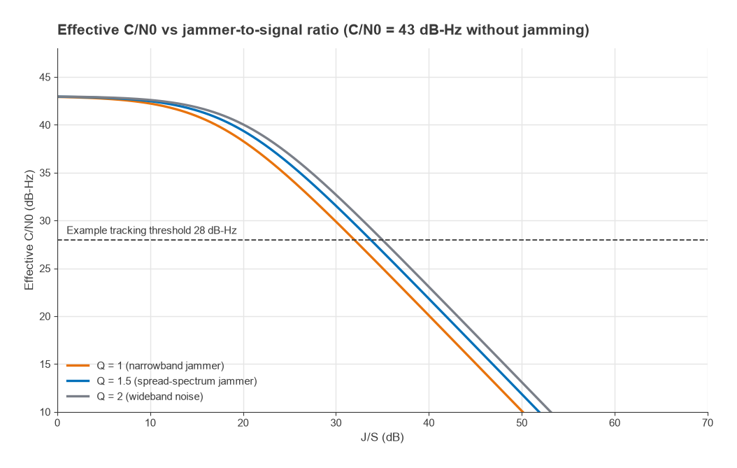
(C/N0)eff = 1 / [1/(C/N0) + (J/S)/(Q · Rc)]
where J/S is the jammer-to-signal power ratio, Rc = 1.023 Mchip/s for L1 C/A, and Q is a spectral factor of about 1 for a narrowband jammer, 1.5 for a spread-spectrum jammer and 2 for wideband noise. Starting from 43 dB-Hz, a narrowband jammer brings C/N0 down to an example tracking threshold of 28 dB-Hz at J/S = 32 dB, as Figure 4 shows. With the signal at −130 dBm, that is a jammer of only about −98 dBm at the antenna. Low-cost in-vehicle jammers radiate far more than that, which is why interference-tolerant designs add techniques outside the RF chain: adaptive notch filters in the digital front end, enough ADC resolution to keep a jammer from saturating the converter, multi-frequency reception, and for critical uses, controlled-pattern antenna arrays that steer nulls toward the interference.
The LNA must also survive. Sufficient linearity keeps a strong jammer from compressing the chain and blinding the receiver to signals from other bands, and protection against electrostatic discharge and nearby high-power transmitters belongs at the antenna input.
How to Design a GPS Front End, Step by Step
- List the bands to receive (for example GPS L1 alone, or L1 plus L5, Galileo E1 and E5a, BeiDou B1) and the filter bandwidth each needs.
- Survey the interference: every transmitter in the product and its frequencies, power and harmonics, plus the likely external environment.
- Decide the order of the first LNA and pre-filter from that survey, using the cascade and blocking calculations above.
- Choose LNA1 for noise figure, input compression and intercept point together, and match it for minimum noise rather than maximum gain, as described in design of low-noise amplifiers.
- Set the total antenna gain so that cable and receiver add less than about 0.2 dB to the noise figure without exceeding the receiver’s input range.
- Lay out with short, well-grounded RF traces and DC feed filtering, and shield the LNA from on-board digital noise.
- Verify C/N0 with a simulator or live sky, then repeat with the product’s own transmitters active.
For choosing the LNA itself, the selection criteria are set out in how to choose an LNA, and the practical set-up for hobby and SDR receivers, including GNSS, is covered in LNAs for SDR and weak-signal receivers.
Frequently Asked Questions
How do you design a GPS front end?
Place a low-noise amplifier at the antenna, follow it with a SAW or similar band-pass filter and a second gain stage, and size the total gain to overcome the cable. Add a pre-filter ahead of the first LNA if strong nearby transmitters would otherwise overload it, accepting about 1 dB of C/N0.
How much gain should a GPS active antenna have?
Enough that the cable and receiver add little noise, typically 25 to 35 dB for common cable lengths. Check the receiver’s allowed range for antenna gain minus cable loss so that a short cable does not overload its input.
Should the SAW filter go before or after the LNA?
After, for the best noise figure in a quiet environment. Before, when co-located transmitters or known interferers would compress the LNA. In the worked example the pre-filter raises noise figure from 1.16 to 2.36 dB.
Why is GPS so easy to jam?
The signal arrives at about −130 dBm. In the example, a narrowband jammer only 32 dB stronger, about −98 dBm, is enough to push C/N0 below a typical tracking threshold.
Related Topics
The RF design applications hub links the other application pages, including software-defined radio and LoRa network planning. Filter technology choices are compared in SAW vs BAW filters, and the overall budget method is in the RF link budget part of Radio Architectures.