

Noise temperature is a way of expressing noise power as the physical temperature of a matched resistor that would deliver the same available power, N = kTB. Engineers use it instead of noise figure when the source is much colder than 290 K, as with antennas pointed at the sky, because noise temperatures add directly and do not assume a 290 K source.
The same idea describes three quantities that appear together in every low-noise receiving system: the equivalent noise temperature Te of an amplifier or receiver, the antenna temperature TA that represents the noise collected from the sky and ground, and the system noise temperature Tsys that combines them. Their ratio to antenna gain gives the G/T figure of merit used throughout satellite communications. This page is part of the noise in RF systems section of the RF design map.
Definition of Equivalent Noise Temperature
The available noise power from a resistor at temperature T in bandwidth B is kTB, as derived on the thermal noise and kTB page. Any noise source with a flat spectrum can therefore be described by the temperature T = N/(kB) that produces the same power. For a two-port such as an amplifier, the equivalent input noise temperature Te is the temperature by which the source would have to be raised to account for all the noise the two-port adds, assuming the two-port itself were noiseless. With gain G, the output noise is
Nout = G k (Ts + Te) B
where Ts is the source temperature. Noise temperature is not the physical temperature of the device; a room-temperature amplifier can have Te of 30 K, while a mixer may have Te of several thousand kelvin.
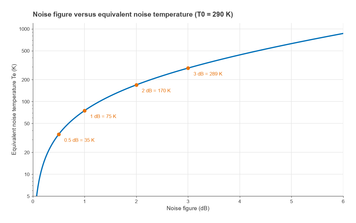
Converting Between Noise Figure and Noise Temperature
Noise factor F is defined with the source at the reference temperature T0 = 290 K. Substituting into the definition gives the conversion
Te = (F − 1) T0 F = 1 + Te/T0 NF = 10 log F
| Noise figure (dB) | Noise factor F | Te (K) |
|---|---|---|
| 0.3 | 1.072 | 20.7 |
| 0.5 | 1.122 | 35.4 |
| 0.7 | 1.175 | 50.7 |
| 1.0 | 1.259 | 75.1 |
| 2.0 | 1.585 | 169.6 |
| 3.0 | 1.995 | 288.6 |
| 6.0 | 3.981 | 864.5 |
| 10.0 | 10.00 | 2610 |
The table shows the main practical reason for the alternative unit: at low noise figures, decibels compress the scale. The step from 0.5 dB to 0.6 dB looks trivial, but it is a change from 35.4 K to 43.0 K, a 21 % increase in the noise the amplifier adds. Low-noise amplifier specifications for satellite and radio astronomy work are therefore often written in kelvin.
Cascades in Noise Temperature
The Friis formula takes a simpler form in temperature:
Te,total = Te1 + Te2/G1 + Te3/(G1G2) + …
An LNA with Te = 35 K and 30 dB of gain, followed by a receiver with 6 dB noise figure (864.5 K), gives 35 + 864.5/1000 = 35.9 K. The second stage adds less than 1 K, which is why the first stage of a low noise amplifier chain dominates.
A passive lossy element with loss L (as a power ratio greater than one) at physical temperature Tp has Te = (L − 1)Tp. At 290 K this is the same as saying its noise figure equals its loss. A cooled cable or waveguide adds less noise than its loss would suggest, which is one reason cryogenic receivers cool the input section as well as the amplifier.
Antenna Temperature
An antenna connected to a matched load delivers noise power kTAB, where TA is the antenna noise temperature. TA is a weighted average of the brightness temperature of everything in the antenna pattern, weighted by the pattern itself. It does not depend on the physical temperature of the antenna, apart from its ohmic losses. Typical contributions include:
- Atmosphere: oxygen and water vapour absorb and re-radiate. Clear-sky noise in the low microwave bands is typically a few kelvin at zenith and rises at low elevation and near the 22 GHz water vapour and 60 GHz oxygen lines.
- Ground: the earth is close to 290 K. Sidelobes and spillover that see the ground add tens of kelvin to a dish that would otherwise see cold sky.
- Cosmic and galactic noise: the cosmic background is about 2.7 K. Galactic noise rises steeply at lower frequencies and typically dominates below roughly 1 GHz.
- Sun, moon and rain: the sun in the main beam can raise TA enough to interrupt a link for minutes. Rain both attenuates and adds noise.
An absorbing medium with loss L at physical temperature Tp in front of a source of temperature Tin produces Tout = Tin/L + Tp(1 − 1/L). A rain cell with 0.5 dB of attenuation at roughly 290 K therefore adds about 31.5 K of sky noise while also reducing the wanted signal by 0.5 dB, which is why rain fade in satellite links is worse than the path loss alone suggests. A terrestrial antenna looking at the horizon, in contrast, sees an antenna temperature close to 290 K, so noise figure based on T0 describes it well. Antenna parameters and Radio Architectures Part 17 cover gain and patterns in more depth.
System Noise Temperature
The system noise temperature combines the antenna, any loss between antenna and LNA, and the receiver, all referred to one reference point. Referred to the antenna terminals, with a feed loss L at physical temperature Tp and a receiver of equivalent noise temperature Te:
Tsys = TA + (L − 1)Tp + L·Te
The total noise power is kTsysB, and the receiver’s carrier-to-noise ratio follows directly. Moving the reference point changes Tsys and the gain by the same factor, so C/N is unchanged; the only requirement is to use one reference point consistently.
Worked Example: G/T of a Ku-Band Terminal
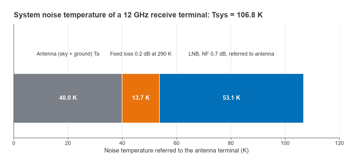
Consider a 1.2 m receive dish at 12 GHz with 65 % aperture efficiency, an assumed clear-sky antenna temperature of 40 K, a 0.2 dB feed loss at 290 K, and an LNB with 0.7 dB noise figure.
- Wavelength: λ = c/f = 0.02498 m.
- Gain: G = η(πD/λ)2 = 0.65 × (150.9)2 = 14,800, or 41.7 dBi.
- Feed loss contribution: (100.02 − 1) × 290 = 13.7 K.
- LNB: Te = 290(100.07 − 1) = 50.7 K, multiplied by L = 1.047 to refer it to the antenna: 53.1 K.
- Tsys = 40 + 13.7 + 53.1 = 106.8 K, or 20.3 dBK.
- G/T = 41.7 − 20.3 = 21.4 dB/K.
Removing the feed loss entirely, by mounting the LNB at the feed horn, would give Tsys = 90.7 K and G/T = 22.1 dB/K. That 0.7 dB improvement comes from a loss of only 0.2 dB, because the loss both attenuates the signal and adds 290 K-class noise to a system whose other contributions are much colder.
From G/T to Carrier-to-Noise Density
G/T enters the satellite link budget through the carrier-to-noise density ratio
C/N0 (dB-Hz) = EIRP − Lpath + G/T − 10 log k = EIRP − Lpath + G/T + 228.6
where 10 log k = −228.6 dBW/K/Hz. With an assumed downlink EIRP of 50 dBW and a slant range of 38,000 km, the free-space path loss at 12 GHz is 205.6 dB. Then C/N0 = 50 − 205.6 + 21.4 + 228.6 = 94.4 dB-Hz, and in a 30 MHz noise bandwidth C/N = 94.4 − 74.8 = 19.6 dB, before atmospheric losses, pointing loss and margins. The satellite RF design page puts these terms in context.
When to Use Noise Temperature Instead of Noise Figure
Noise figure is defined as the SNR degradation through a device when the source is at 290 K. When the real source temperature TA differs, the actual degradation is
SNRin/SNRout = 1 + Te/TA
An LNA with NF = 0.5 dB (Te = 35.4 K) degrades the SNR by exactly 0.5 dB from a 290 K source. From a 50 K antenna it degrades the SNR by 10 log(1 + 35.4/50) = 2.3 dB, and from a 10 K source by 6.6 dB. Noise figure describes the device correctly in all three cases, but it describes the system only in the first.
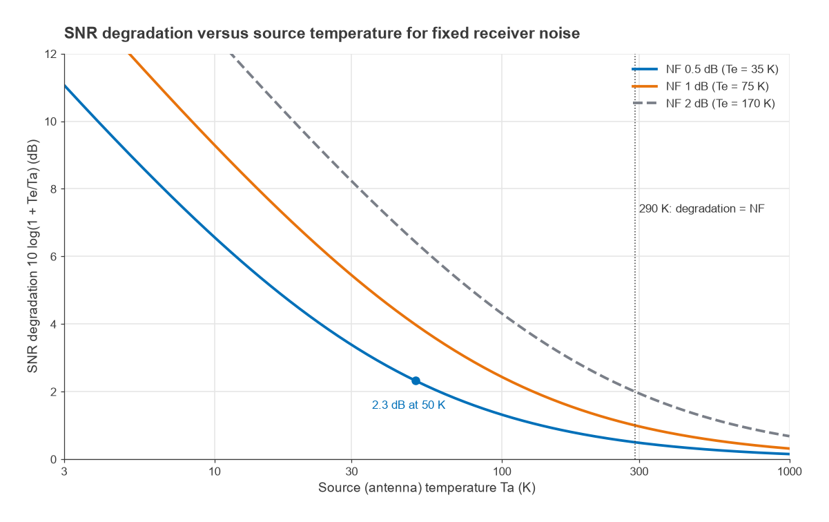
The practical rule is simple. Use noise figure for terrestrial links, cabled test setups and any chain where the source sits near room temperature, because it plugs straight into −174 dBm/Hz + NF + 10 log B and the sensitivity calculation. Use noise temperature for satellite ground stations, deep-space and radio astronomy receivers, GNSS antennas looking at open sky, and any calculation that mixes cold sources, cooled components or lossy elements at temperatures other than 290 K.
Measuring Noise Temperature
The Y-factor method measures the output noise power ratio Y with a calibrated noise source switched between a hot state Th and a cold state Tc:
Te = (Th − Y Tc) / (Y − 1)
A noise source with an excess noise ratio of 15 dB has Th = 290 × (1 + 31.6) = 9,461 K. If the device shows Y = 14.0 dB (25.1) with Tc = 290 K, then Te = (9,461 − 25.1 × 290)/24.1 = 90 K, or NF = 1.18 dB. For very low-noise devices a cold load in liquid nitrogen, near 77 K, improves accuracy. The procedure and its error sources are described in noise figure measurement.
Frequently Asked Questions
When should noise temperature be used instead of NF?
Use noise temperature when the source is not near 290 K, typically an antenna looking at the sky, or when the noise figure is below about 1 dB and small differences matter. Temperatures of the antenna, losses and receiver add directly to give the system temperature and G/T.
What is G/T?
G/T is the ratio of receive antenna gain to system noise temperature, expressed in dB/K. It summarises the sensitivity of a receiving station in a single number. A higher G/T gives a proportionally higher carrier-to-noise density ratio for the same incoming signal.
How do you convert noise figure to noise temperature?
Convert the noise figure in dB to the noise factor F = 10NF/10, then Te = (F − 1) × 290 K. A 1 dB noise figure corresponds to 75 K and 3 dB to about 289 K.
Is antenna temperature the physical temperature of the antenna?
No. It represents the noise the antenna collects from its surroundings, weighted by its radiation pattern. Only the ohmic loss of the antenna adds noise related to its physical temperature.
Related Topics
Continue with noise figure, cascaded noise figure and kTB for the underlying definitions, then satellite RF design and the link budget for applications. The noise hub lists every topic in this section, and the wireless terms glossary covers the abbreviations.