

An IQ modulator is a quadrature upconverter that combines two baseband signals, in-phase (I) and quadrature (Q), onto one RF carrier by mixing them with two copies of the local oscillator (LO) 90° apart and summing the results: s(t) = I(t)cos ωt − Q(t)sin ωt. Because the two carriers are orthogonal, any amplitude and phase can be produced, which lets one circuit generate QAM, PSK, OFDM or single-sideband signals. An IQ demodulator performs the reverse operation.
Quadrature modulators and demodulators sit at the boundary between digital baseband and RF in almost every modern radio. They are the core of direct-conversion transmitters and zero-IF receivers, and the same structure underlies image-reject mixers. This page explains how they work, how the quadrature LO is generated, and how gain imbalance, phase error and LO leakage show up as sideband and carrier spurs and as EVM. It belongs to the RF mixers section of the RF design reference.
How an IQ modulator works
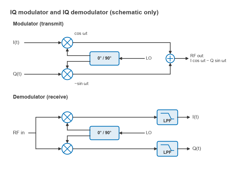
Figure 1 shows the structure. The I signal multiplies cos ωt, the Q signal multiplies −sin ωt, and the two products are summed. Writing the baseband pair as a complex envelope z(t) = I(t) + jQ(t), the RF output is
s(t) = Re{z(t)ejωt} = I(t)cos ωt − Q(t)sin ωt = |z(t)| cos(ωt + ∠z(t))
The magnitude of z sets the RF amplitude and its angle sets the RF phase. Any point on the constellation diagram maps to a unique carrier amplitude and phase, so a digital baseband only has to produce the I and Q sample streams, usually through a pair of DACs as described in Radio Architectures Part 11. Standard formats such as QAM fall out directly.
A useful special case is the single-sideband (SSB) test. With I = cos ωmt and Q = sin ωmt, the envelope is z = ejωmt and the output is a single tone at ω + ωm. Reversing the sign of Q moves the tone to ω − ωm. In a perfect modulator, the other sideband and the carrier are absent. Real modulators leave residues of both, and measuring them is the standard way to characterise a modulator.
How an IQ demodulator works
The demodulator splits the received RF signal into two paths and mixes them with cos ωt and −sin ωt from the same quadrature LO. For an input I cos ωt − Q sin ωt:
- Multiplying by 2cos ωt gives I + I cos 2ωt − Q sin 2ωt; lowpass filtering leaves I.
- Multiplying by −2sin ωt gives Q − Q cos 2ωt − I sin 2ωt; lowpass filtering leaves Q.
The lowpass filters remove the components at twice the carrier and set the channel bandwidth. If the LO is offset from the carrier by Δω or by a phase φ, the recovered envelope rotates as z·e−j(Δωt + φ), which the digital receiver must track. In a zero-IF receiver the demodulator is the downconverter; in a low-IF receiver it produces a complex IF that is then shifted digitally.
Generating the quadrature LO
Both functions depend on two LO signals exactly 90° apart with equal amplitude. Several methods are common:
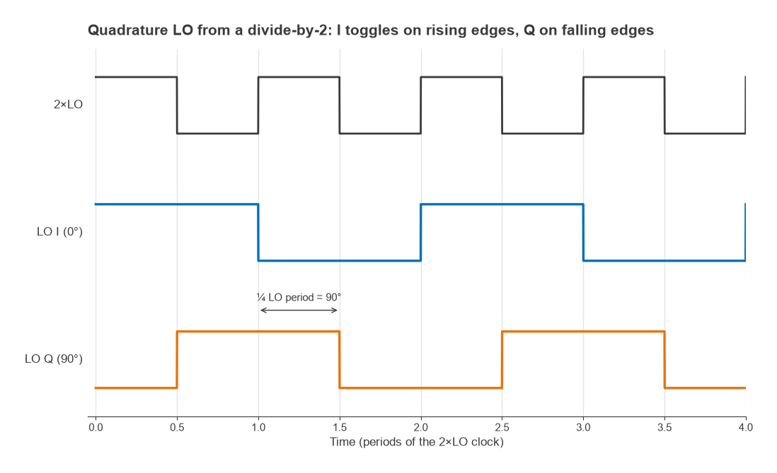
- Divide-by-2 from a 2×LO source. Two flip-flops clocked on opposite edges of a signal at twice the LO frequency produce square waves offset by a quarter of the LO period, which is 90° (Figure 4). Phase accuracy depends on the clock’s duty cycle and on matching between the flip-flops, not on component values, so it holds over a wide frequency range. This is the usual choice in integrated transceivers.
- RC-CR or polyphase networks. A single RC-CR pair gives exactly 90° at all frequencies but equal amplitudes only at f = 1/(2πRC). Cascaded polyphase stages widen the band of good amplitude match.
- Quadrature hybrid couplers. At microwave frequencies a branch-line or Lange coupler splits the LO into 0° and 90° outputs, covered on the hybrid couplers page.
- Digital generation. When the carrier is low enough, the quadrature carriers can be computed numerically, which removes analog imbalance entirely.
The LO’s phase noise passes directly onto the modulated signal, so the quadrature generator is normally fed from a low-noise PLL synthesizer.
Sideband suppression and IQ imbalance
If the Q path has a relative gain g and its LO is off quadrature by θ, the output envelope becomes z’ = I + jgQejθ. This can be rewritten as a sum of the wanted envelope and its complex conjugate:
z’ = [(1 + gejθ)/2]·z + [(1 − gejθ)/2]·z*
The conjugate term is the unwanted sideband, a mirror image of the signal reflected about the carrier. Its level relative to the wanted sideband is the sideband suppression:
Sideband suppression (dB) = 20log10(|1 + gejθ| / |1 − gejθ|)
This is the same expression as the image rejection ratio of an image-reject mixer, discussed on the image frequency page, because the two problems are mathematically identical. The gain imbalance can come from the DACs, baseband filters or mixers, and the phase error from the LO splitter or from unequal delays in the baseband paths.
LO leakage and carrier feedthrough
Any DC offset at the I or Q input is upconverted to a tone at exactly the LO frequency. Direct coupling of the LO to the RF port adds to it. The result is a carrier spur in the middle of the signal, called LO leakage or carrier feedthrough. For DC offsets VI and VQ and a baseband signal amplitude A,
LO leakage (dBc) = 20log10(√(VI2 + VQ2) / A)
Because the DC offset produces a fixed tone, it is independent of the signal, so leakage measured in dBc gets worse as the output power is turned down. Transmitters with a wide power control range therefore calibrate it by adding small correction offsets to the DACs until the carrier is minimised, often repeating the calibration across temperature and gain settings.
Worked example
An IQ modulator is driven with a 1 MHz SSB test tone of 0.5 V peak per path. The Q path is 0.2 dB high in gain and its LO is 2° off quadrature. The baseband has DC offsets of 5 mV on I and 3 mV on Q.
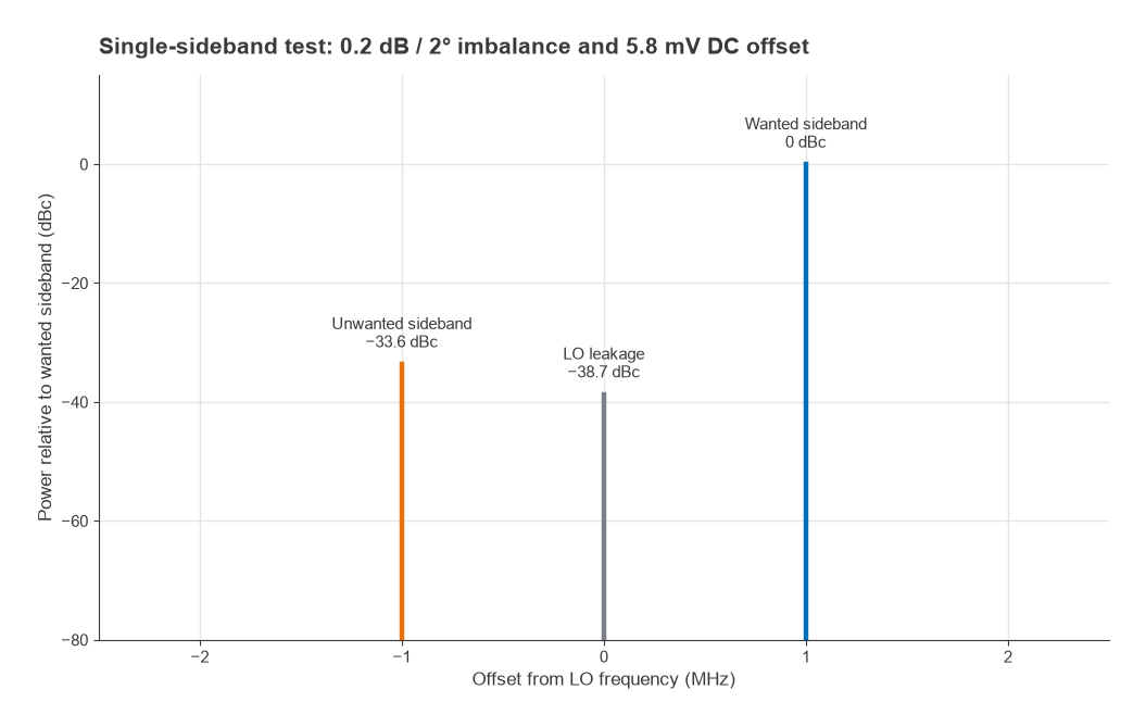
- Sideband suppression: g = 100.2/20 = 1.023, θ = 2°, giving 20log(|1 + gejθ|/|1 − gejθ|) = 33.6 dB
- LO leakage: √(52 + 32) = 5.83 mV, and 20log(5.83/500) = −38.7 dBc
- EVM from the sideband term: |1 − gejθ|/|1 + gejθ| = 2.09%
- EVM from LO leakage: 5.83/500 = 1.17%
- Combined (root sum of squares): 2.39%, equivalent to a 32.4 dB signal-to-impairment ratio
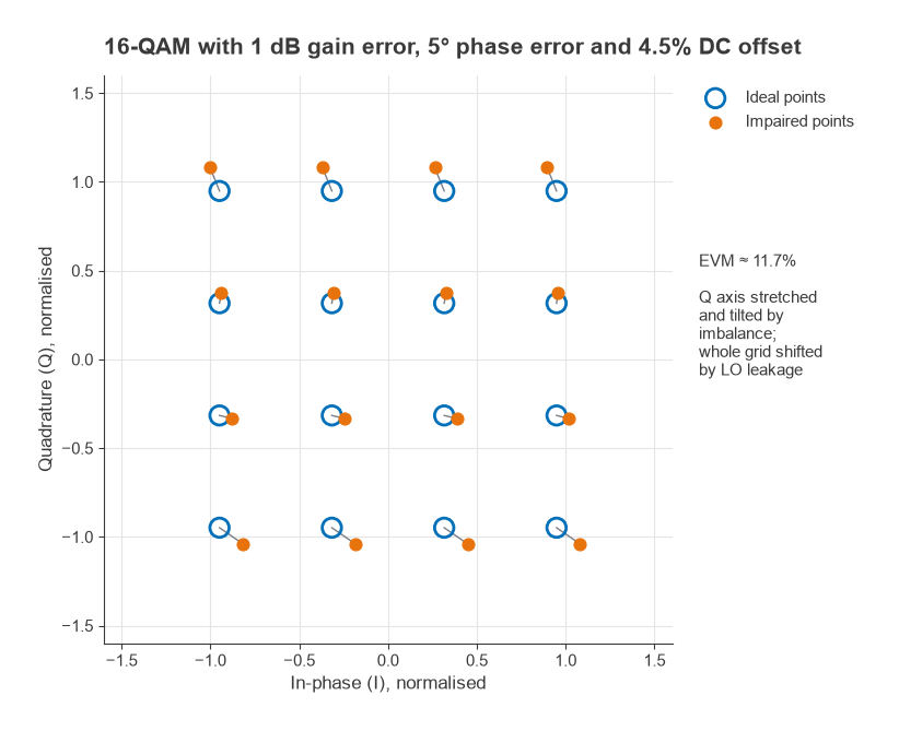
Figure 2 shows the resulting spectrum. Bringing leakage to −40 dBc at this signal level requires the total offset to stay below 5 mV. Figure 3 shows larger impairments (1 dB, 5° and a DC offset of 4.5% of the RMS signal) applied to 16-QAM, which give about 11.7% EVM. The Q axis is stretched and tilted, and the whole grid is shifted by the leakage. The Radio Architectures Part 16 article explains how such EVM contributions combine with noise and nonlinearity in a transmitter budget.
Demodulator-specific impairments
An IQ demodulator suffers the same gain and phase imbalance, which mixes each received signal with its own mirror. In a direct-conversion receiver it also faces DC offsets created by LO self-mixing: LO energy that leaks to the RF port is mixed with the LO itself and produces a DC term, which can be time-varying if the leakage reflects off the antenna. Even-order distortion converts strong amplitude-modulated blockers to baseband. These effects are covered in detail on the zero-IF receivers page. Modern receivers estimate and remove most of the static imbalance and offset digitally.
Where IQ modulators are used
Direct-conversion transmitters use a single IQ modulator to go from baseband straight to the RF channel, which removes the IF filters and second LO of a superheterodyne design. Heterodyne transmitters may use an IQ modulator at a fixed IF followed by an upconverting mixer. Test equipment such as vector signal generators uses the same structure with careful calibration. The modulator is also a basic building block of single-sideband transmitters, where its sideband suppression directly sets the unwanted-sideband level.
Frequently asked questions
How does an IQ modulator work?
It multiplies the I signal by a cosine carrier and the Q signal by a negative sine carrier at the same frequency, then adds the two. The result is I cos ωt − Q sin ωt, a carrier whose amplitude and phase follow the complex number I + jQ.
What causes the unwanted sideband in an IQ modulator?
Gain mismatch between the I and Q paths and phase error in the quadrature LO. Together they create a mirror image of the signal about the carrier. A 0.2 dB, 2° mismatch leaves the unwanted sideband 33.6 dB below the wanted one.
What is LO leakage?
LO leakage is a tone at the carrier frequency caused by DC offsets in the baseband paths and by direct LO feedthrough to the RF port. It is usually reduced by calibrating small correcting DC offsets into the DACs.
What is the difference between an IQ modulator and a mixer?
A single mixer translates one real signal in frequency and produces both sidebands. An IQ modulator uses two mixers with quadrature LOs, so it can select one sideband and set any amplitude and phase.
Related topics
Related pages include mixer types, image frequency and image-reject mixers and frequency planning and spurs. For system context, see transmitter architectures, zero-IF receivers, the digital modulation overview and the wireless terms glossary.