

The image frequency is the unwanted input frequency that a mixer converts to the same intermediate frequency (IF) as the wanted signal. It lies on the opposite side of the local oscillator (LO) from the wanted signal, at the same offset, so fimage = fRF ± 2fIF. Image rejection is the receiver’s ability to suppress this second response, using filters before the mixer, an image-reject mixer, or both.
Every superheterodyne receiver has an image problem, and the choice of IF, LO side and mixer architecture is largely a choice of how to deal with it. This page derives the image frequency, shows why filtering alone becomes difficult at low IFs, explains the Hartley and Weaver image-reject mixers, and quantifies how gain and phase mismatch limit their performance. It is part of the RF mixers section of the RF design reference.
Where the image frequency comes from
An ideal mixer multiplies the input by the LO. A cosine at fRF times a cosine at fLO produces components at fLO + fRF and |fLO − fRF|. The difference term is the IF. Because only the magnitude of the difference matters, two input frequencies produce the same IF: one at fLO − fIF and one at fLO + fIF. One is the wanted signal and the other is the image.
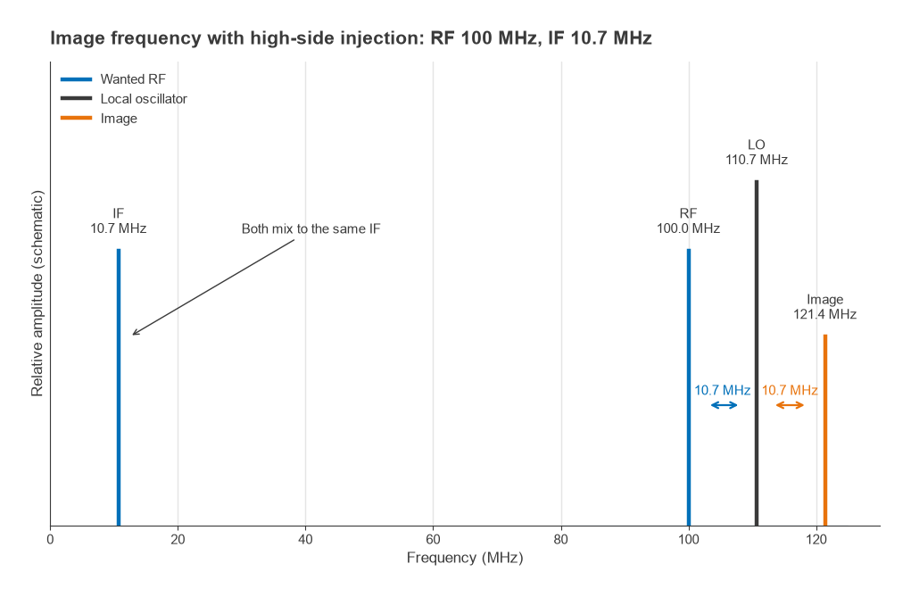
- High-side injection (fLO = fRF + fIF): fimage = fRF + 2fIF
- Low-side injection (fLO = fRF − fIF): fimage = fRF − 2fIF
The image is always 2fIF away from the wanted signal. For a 100 MHz FM broadcast signal and the traditional 10.7 MHz IF with high-side injection, the LO is at 110.7 MHz and the image at 121.4 MHz (Figure 1). After the mixer, a signal at 121.4 MHz is indistinguishable from one at 100 MHz. No amount of IF filtering can separate them, so the image must be removed before or within the mixer. With high-side injection the IF spectrum is also inverted relative to the RF spectrum, which matters for single-sideband and some digital formats.
Rejecting the image by filtering
The classic approach is a preselector: a bandpass filter ahead of the mixer that passes the wanted band and attenuates the image band. Its job gets easier as the IF rises, because the image moves further from the passband. The cost is that a higher IF makes narrow channel filtering harder, which is one reason many receivers use two conversions: a high first IF to place the image far away, then a lower second IF for channel selection. The frequency planning page covers how these choices interact with other spurious responses, and LC filter design covers the filters themselves.
Worked example: a fixed FM-band preselector
Consider a receiver for 88 to 108 MHz with a 10.7 MHz IF and high-side injection, using a fixed Butterworth bandpass preselector that covers the whole band. Its geometric centre is f0 = √(88 × 108) = 97.5 MHz and its bandwidth is 20 MHz. The bandpass-to-lowpass transformation gives a normalised frequency
Ω = (f/f0 − f0/f) · f0/BW, and attenuation A = 10log10(1 + Ω2N) for an N-pole response.
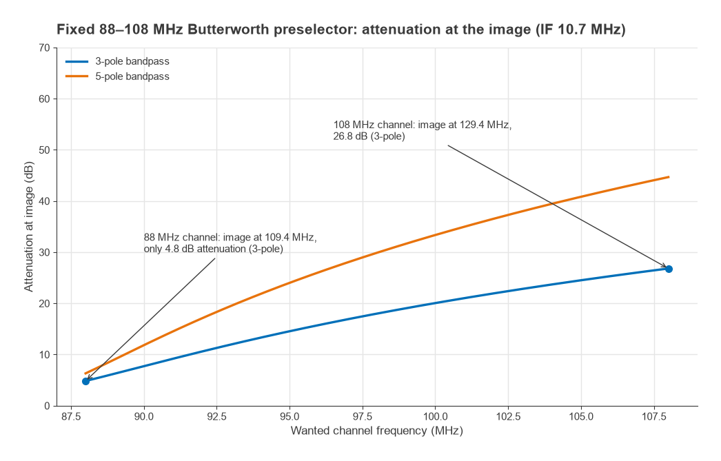
| Wanted channel (MHz) | LO (MHz) | Image (MHz) | 3-pole attenuation (dB) | 5-pole attenuation (dB) |
|---|---|---|---|---|
| 88.0 | 98.7 | 109.4 | 4.8 | 6.3 |
| 98.0 | 108.7 | 119.4 | 18.0 | 29.9 |
| 108.0 | 118.7 | 129.4 | 26.8 | 44.7 |
At the bottom of the band the image falls only 1.4 MHz above the filter’s upper edge, and even a 5-pole filter gives just 6.3 dB of rejection (Figure 2). Above 108 MHz lie aeronautical allocations, so strong signals at the image are realistic. Practical broadcast receivers address this with a tracking preselector that tunes with the LO, which keeps the image a constant distance outside a narrow passband. Raising the IF to 45 MHz would move the lowest-channel image to 178 MHz, where the same fixed 3-pole filter provides about 47.7 dB.
Image-reject mixers
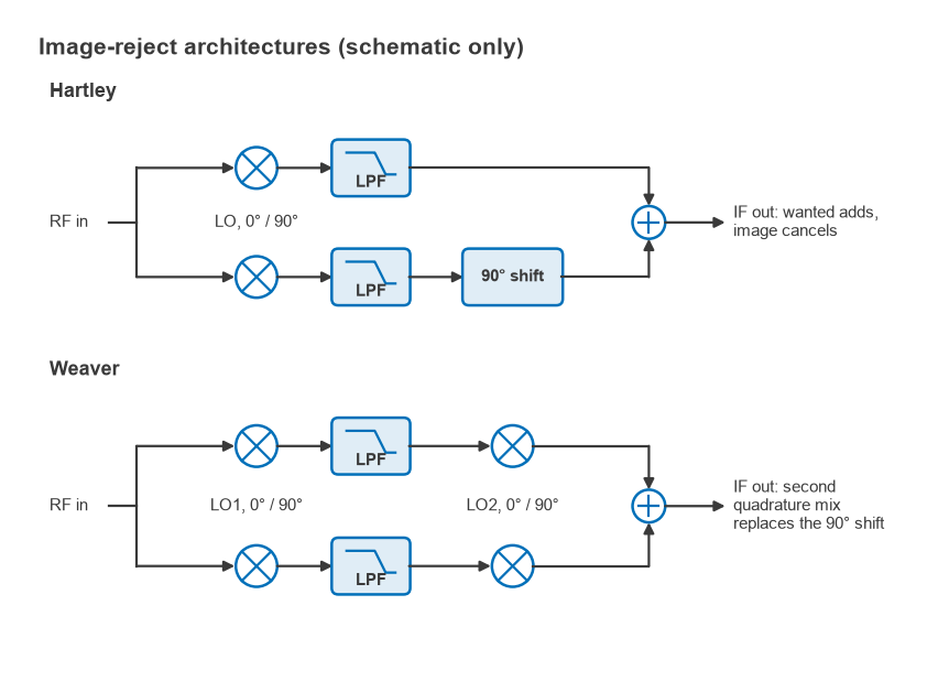
An image-reject mixer separates the wanted signal from the image using phase rather than frequency selectivity. It needs two mixers driven by LOs in quadrature (0° and 90°), which is why it is closely related to the IQ demodulator. Both architectures below exploit the fact that the wanted signal and the image produce IF outputs with opposite phase relationships between the two paths.
Hartley architecture
The Hartley mixer splits the RF input into two paths, mixes one with cos(ωLOt) and the other with sin(ωLOt), lowpass filters both, shifts one path by 90° and sums them (Figure 3). Take a wanted signal A cos(ωRFt) and an image B cos(ωimt) with high-side injection, so ωLO − ωRF = ωIF and ωLO − ωim = −ωIF. After lowpass filtering:
- Cosine path: (A/2)cos(ωIFt) + (B/2)cos(ωIFt)
- Sine path: (A/2)sin(ωIFt) − (B/2)sin(ωIFt)
- Sine path after a +90° shift: (A/2)cos(ωIFt) − (B/2)cos(ωIFt)
- Sum: A cos(ωIFt), with the image term cancelled
Subtracting instead of adding selects the other sideband, so the same hardware can receive either the upper or lower response. The weak point is the 90° phase shifter at IF. A passive RC-CR network gives exactly 90° but equal amplitudes at only one frequency, so wideband Hartley designs use polyphase filters or perform the shift digitally after the ADCs.
Weaver architecture
The Weaver mixer replaces the IF phase shifter with a second pair of quadrature mixers driven by a second LO, then sums the outputs. The quadrature relationship of the second LO performs the same cancellation that the 90° shifter does in the Hartley design, and mixers are easier to match over a wide band than phase-shift networks. The trade-off is a secondary image: the second mixing stage has its own image, which the lowpass filters between the stages must attenuate. Weaver structures suit integrated receivers where well-matched mixer pairs are cheap and the second LO can be derived from the first.
How mismatch limits image rejection
Cancellation is only as good as the match between the two paths. With a relative gain error of (1 + ε) and a phase error θ from perfect quadrature, the image rejection ratio (IRR) is
IRR = [1 + 2(1 + ε)cosθ + (1 + ε)2] / [1 − 2(1 + ε)cosθ + (1 + ε)2]
For small errors this reduces to IRR ≈ 4/(ε2 + θ2), with θ in radians. Some numbers (Figure 4):
| Gain error (dB) | Phase error (°) | IRR (dB) |
|---|---|---|
| 0 | 1 | 41.2 |
| 0.1 | 0 | 44.8 |
| 0.1 | 1 | 39.6 |
| 0.2 | 2 | 33.6 |
| 0.5 | 3 | 28.2 |
| 1.0 | 5 | 22.8 |
Reaching 40 dB with no gain error requires the phase to be within about 1.15° of quadrature, and this must hold across the band, over temperature and from part to part. That is why uncalibrated analog image-reject mixers typically achieve somewhere around 25 to 40 dB. Higher figures generally rely on calibration, often by adjusting gain and phase in the digital domain after the ADCs.
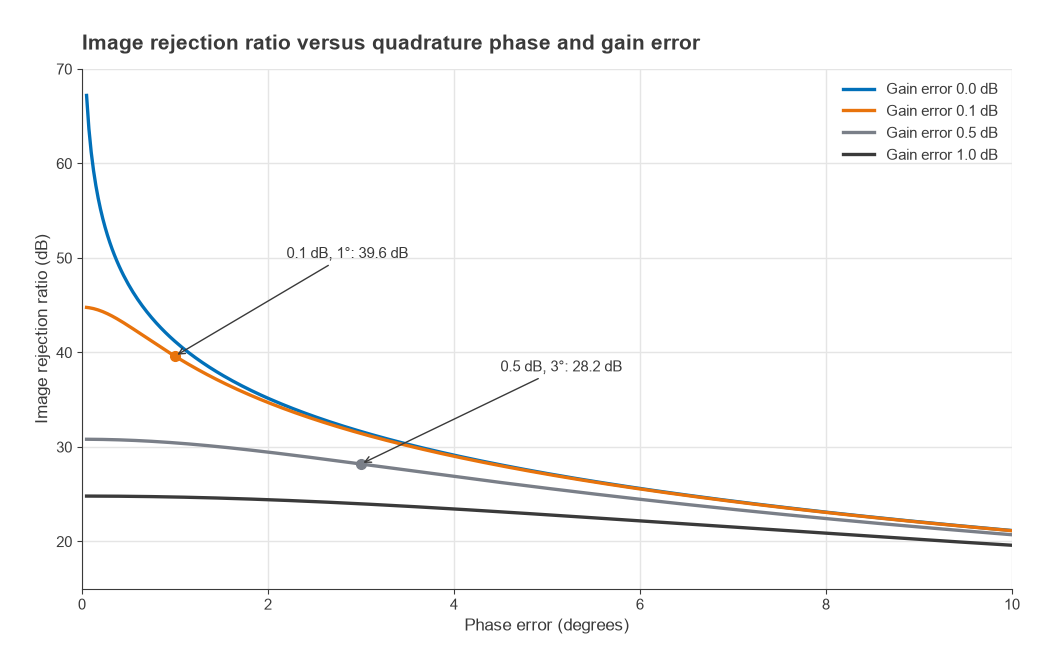
Image rejection in dB from independent mechanisms adds. A preselector providing 30 dB at the image ahead of an image-reject mixer with 35 dB IRR gives about 65 dB in total, which is why many receivers combine moderate filtering with a moderate IRR rather than relying on either alone.
Images in low-IF and zero-IF receivers
In a low-IF receiver, the IF is comparable to the channel spacing, so the image is often the adjacent or alternate channel. No RF filter can remove it, and the receiver depends entirely on quadrature downconversion followed by complex (polyphase or digital) filtering. If the adjacent channel is 20 dB stronger than the wanted signal and the demodulator needs 15 dB SNR, the IRR must exceed 35 dB. In a zero-IF receiver, the image is the wanted signal’s own mirror spectrum, so IQ imbalance appears as self-interference that limits EVM rather than as a separate channel. The receiver architecture comparison sets these trade-offs side by side.
Frequently asked questions
What is the image frequency?
It is the second input frequency that a mixer converts to the same IF as the wanted signal. It sits on the other side of the LO at the same offset, 2fIF from the wanted signal. With a 100 MHz signal, a 10.7 MHz IF and high-side injection, the image is at 121.4 MHz.
How do image-reject mixers work?
They mix the input with two LOs 90° apart. The wanted signal and the image emerge from the two paths with opposite phase relationships, so after a further 90° shift (Hartley) or a second quadrature mixing stage (Weaver), summing the paths reinforces the wanted signal and cancels the image.
How much image rejection does a receiver need?
Enough that the strongest expected signal at the image frequency, after rejection, falls below the wanted signal by more than the required SNR. Requirements commonly fall in the 40 to 80 dB range depending on the band and standard, usually met by combining filtering with an image-reject or IQ architecture.
Does a higher IF improve image rejection?
Yes, for filter-based rejection. The image moves 2fIF away from the wanted signal, so a higher IF puts it further into the preselector’s stopband. The cost is harder channel filtering at the higher IF.
Related topics
Mixer circuits and their trade-offs are covered in mixer types, and the quadrature hardware in IQ modulators and demodulators. For the wider receiver picture, see Radio Architectures Part 2: receivers, LOs and mixers, frequency planning and spurs, the RF filters section and the wireless terms glossary.