

A 5G RF front end is the set of circuits between the antennas and the transceiver of a 5G NR device: antenna tuners, switches, filters, duplexers and multiplexers, power amplifiers and low-noise amplifiers. It differs from earlier cellular front ends in the number of bands and simultaneous paths it must support, including new wide TDD bands below 7 GHz, LTE and NR uplinks transmitting at the same time, and phased-array modules for millimetre-wave bands.
This page describes what sits in a 5G NR front end, how the FR1 and FR2 frequency ranges shape the hardware, why dual connectivity creates new interference problems, and how filter and amplifier counts build up in a multi-band handset. It belongs to the RF design by application section of the RF design guide. The module-level view of the same hardware is in RF front-end modules.
What Is in a 5G RF Front End
Following the signal from the antenna inward, a typical FR1 handset front end contains the following functions.
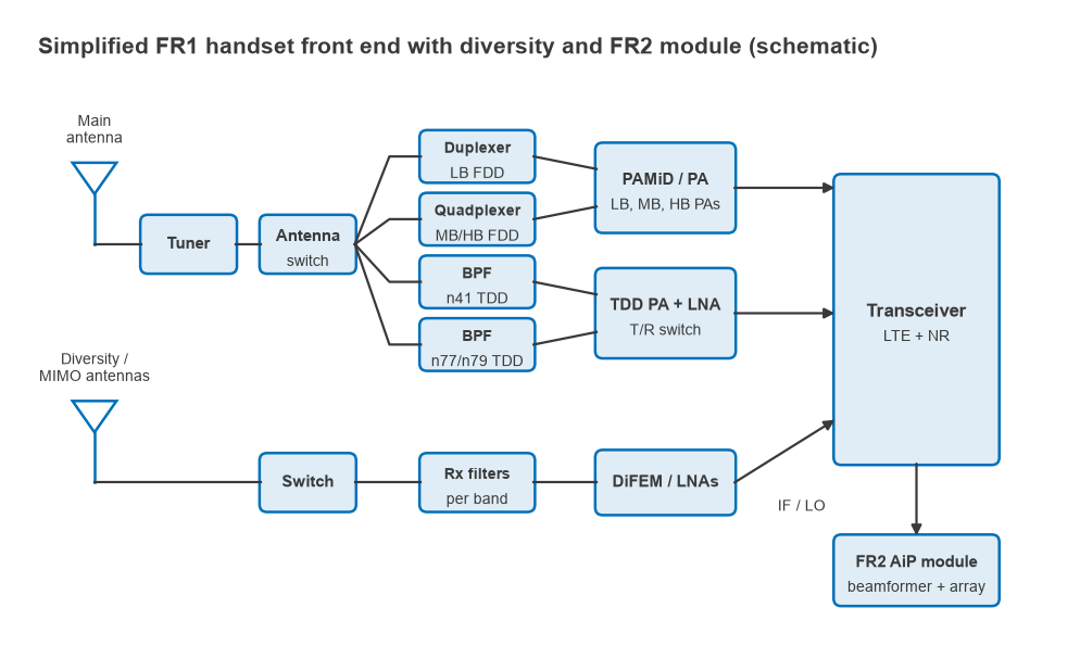
- Antenna tuners: switched capacitors or inductors that retune small handset antennas across bands and compensate for detuning by the user’s hand.
- Antenna switches: multi-throw switches that route each antenna to the right band path, and in TDD bands switch the transmitter across several antennas for sounding reference signals.
- Filters, duplexers and multiplexers: acoustic SAW and BAW devices for most bands below about 3 GHz, with BAW, LTCC or other technologies in the wide 3 to 5 GHz bands. See SAW vs BAW filters and duplexer vs diplexer.
- Power amplifiers: one per group of nearby bands, usually integrated with filters and switches in a PA module.
- Low-noise amplifiers: on the main path and on every diversity and MIMO receive path, often integrated with filters in receive modules.
- Couplers and detectors: for transmit power control and antenna impedance sensing.
Handset makers buy most of these as modules. Common categories include PA modules with integrated duplexers (often called PAMiD), versions that also include LNAs, diversity receive modules (DiFEM or LFEM types) and, for FR2, antenna-in-package modules that combine a beamforming IC with a small patch array. The names vary between suppliers, but the partitioning by frequency range and by transmit or receive path is fairly consistent.
FR1 and FR2 Frequency Ranges
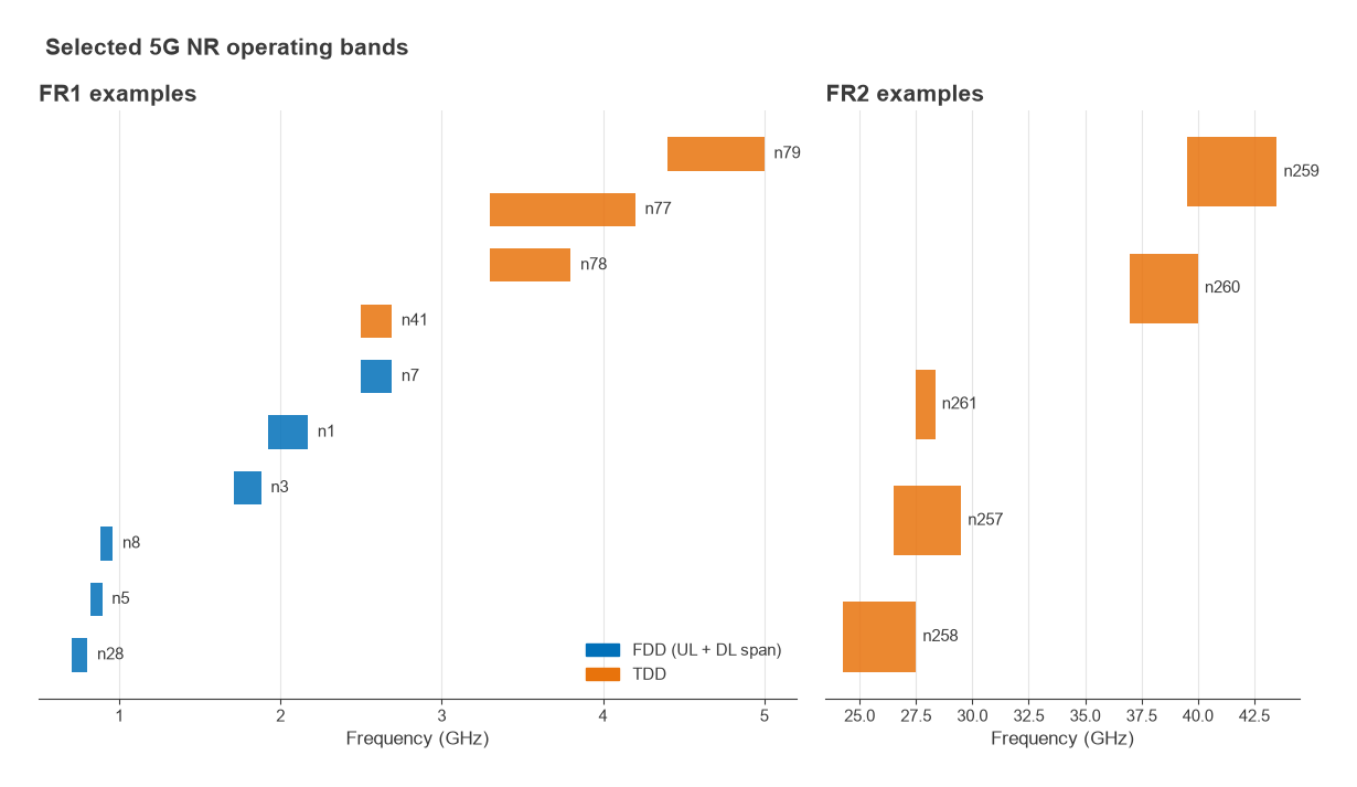
NR defines two main frequency ranges. FR1 covers roughly 410 MHz to 7.125 GHz and includes both refarmed LTE bands and new NR bands. FR2 covers roughly 24.25 to 52.6 GHz, with later releases extending millimetre-wave operation further. Exact band edges are set in the 3GPP specifications and are updated between releases, so a front-end design should always start from the current band tables.
FR1: wide TDD bands and wider channels
Most FR1 refarmed bands are FDD, so they need a duplexer that keeps the transmitter out of the receiver. The new mid-band NR allocations, such as n77 (3.3 to 4.2 GHz), n78 (3.3 to 3.8 GHz) and n79 (4.4 to 5.0 GHz), are TDD and use a single band-pass filter with a transmit/receive switch. They are much wider than LTE bands in both absolute and fractional terms: n77 spans 900 MHz, about 24% of its centre frequency, which makes acoustic filter design harder and pushes some designs toward other filter technologies.
Channels are wider as well. An FR1 carrier can occupy up to 100 MHz. With 30 kHz subcarrier spacing and 273 resource blocks of 12 subcarriers, the occupied bandwidth is 273 × 12 × 30 kHz = 98.28 MHz. That bandwidth raises the noise floor and places tighter demands on PA linearity and on the flatness of every filter in the path.
FR2: millimetre-wave arrays
At FR2 frequencies the free-space path loss for a given antenna gain is much higher and a single handset antenna cannot close the link, so FR2 front ends use phased arrays. Each element has its own small PA, LNA and phase shifter, and the beamforming IC sits directly under the antenna to avoid lossy interconnect. Carrier bandwidths of up to 400 MHz are allowed. The design problems are those described in mmWave radio architectures and MIMO, beamforming and phased arrays.
EN-DC and Simultaneous Uplinks
E-UTRA NR Dual Connectivity (EN-DC) lets a device connect to an LTE anchor carrier and an NR carrier at the same time. Many early 5G networks were deployed this way, and the front end must then run an LTE transmitter and an NR transmitter simultaneously. Two transmitters through nonlinear switches, PAs and antennas generate harmonics and intermodulation products, and some of those land in the device’s own receive bands.
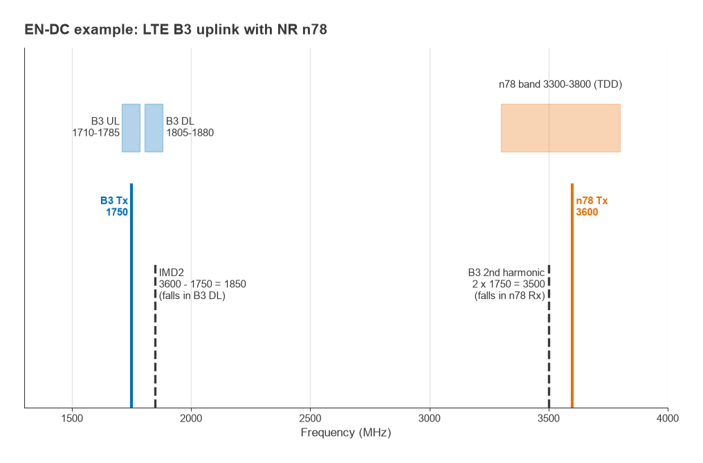
Take the combination of LTE Band 3 (uplink 1710 to 1785 MHz, downlink 1805 to 1880 MHz) with NR n78. With the LTE carrier at 1750 MHz and the NR uplink at 3600 MHz:
- The second harmonic of the Band 3 transmitter, 2 × 1750 = 3500 MHz, falls inside n78. When n78 is receiving, that harmonic can desensitise it unless the B3 path has enough harmonic filtering.
- The second-order intermodulation product, 3600 − 1750 = 1850 MHz, falls inside the Band 3 downlink, where it acts as in-band interference to the LTE receiver.
Neither product can be removed by filtering after it is generated, so the front end has to prevent it: harmonic traps after the PA, high linearity in the antenna switch and tuner, good isolation between the two PA outputs, and antenna placement that couples the two transmitters weakly. The specifications include relaxations of receiver sensitivity for some band combinations, and for difficult combinations networks can schedule the two uplinks so they do not transmit at once. The mechanisms are the same as in intermodulation and intercept points and receiver blocking and desense.
Transmit and Receive Budgets
Worked example: PA output power
A power class 3 handset targets about 23 dBm at the antenna connector; power class 2, used in several TDD bands, targets about 26 dBm. Every component after the PA subtracts from that. Assume 0.3 dB for the PA output match and coupler, 1.5 dB for the band filter, 0.5 dB for the antenna switch and 0.5 dB for the tuner and routing, a total of 2.8 dB. The PA must then deliver 23 + 2.8 = 25.8 dBm for class 3, or 28.8 dBm for class 2. NR uplinks using CP-OFDM have a high peak-to-average power ratio, so the PA also needs several dB of headroom or a linearisation scheme; see modulation, EVM and PAPR, power amplifier classes and PA linearization.
Worked example: receive noise figure
On the receive side the same losses come before the LNA. With 0.5 dB of switch loss and 1.5 dB of filter loss ahead of an LNA with 1.2 dB noise figure and 16 dB gain, followed by a transceiver with a 7 dB noise figure, the Friis formula gives
F = Lfront × (FLNA + (FTRX − 1)/GLNA) = 1.585 × (1.318 + 4.012/39.8) = 2.25, or 3.5 dB
For a 98.28 MHz occupied bandwidth the thermal noise floor is −174 + 10 log10(98.28 × 10⁶) = −94.1 dBm, so the receiver input-referred noise is about −90.6 dBm. Every 0.1 dB saved in front-end loss improves this directly, which is why filter insertion loss is one of the most closely watched parameters in a handset design.
Worked example: FR2 array EIRP
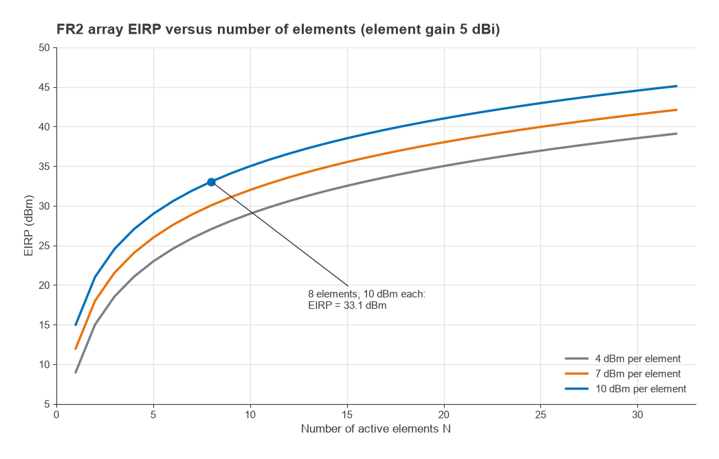
For an array of N elements, each driven with conducted power Pe and each with gain Ge, the peak EIRP in the beam direction is
EIRP = Pe + 10 log10N + Ge + 10 log10N = Pe + 20 log10N + Ge
One 10 log10N comes from adding the element powers and the other from the array gain. With eight elements at 10 dBm and 5 dBi, the total conducted power is 19 dBm but the EIRP is 10 + 18.1 + 5 = 33.1 dBm. Doubling to 16 elements adds 6 dB, giving 39.1 dBm. This is how FR2 modules reach useful EIRP with per-element PAs of only a few milliwatts to tens of milliwatts.
How Many Filters and PAs
The component count in a 5G handset grows with every band, every receive path and every simultaneous combination. A worked count for an illustrative band set makes the scaling clear. Assume eight FDD bands (B1, B3, B5, B7, B8, B20, B28 and B66) and three TDD bands (n41, n77 covering n78, and n79), with 4×4 downlink MIMO in seven of the mid- and high-band bands.
| Path | Basis | Filter functions |
|---|---|---|
| Main transmit/receive, FDD | 8 duplexers × 2 filters | 16 |
| Main transmit/receive, TDD | 3 band-pass filters | 3 |
| Diversity receive | 1 receive filter per band | 11 |
| Extra MIMO receive paths | 2 paths × 7 bands | 14 |
| Total | 44 |
In practice multiplexers combine several of these functions on one die, and some wideband filters serve more than one band, so the number of physical parts is lower. The transmit side needs fewer amplifiers than filters because one broadband PA covers a group of bands: in this example a low-band PA, a mid-band PA, a high-band PA, an n77 PA and an n79 PA, five in all, plus a second n77 PA if the device supports two-layer uplink MIMO. EN-DC adds constraints rather than PAs, because the LTE and NR carriers must be able to run through separate PAs at the same time. Adding a carrier aggregation combination can also require new multiplexers so that two bands share an antenna path without loading each other.
This count is the reason front-end design is as much about integration, layout and coexistence as about individual circuit performance. The board-level issues are covered in RF coexistence, and the receiver side of multi-antenna operation in diversity techniques.
Frequently Asked Questions
What is in a 5G RF front end?
Antenna tuners, antenna switches, filters, duplexers and multiplexers, power amplifiers, low-noise amplifiers, couplers and power detectors, usually packaged as transmit and receive modules. FR2-capable devices add antenna-in-package modules that combine a phased array with a beamforming IC.
What is the difference between FR1 and FR2?
FR1 is the sub-7 GHz range, roughly 410 MHz to 7.125 GHz, and uses conventional antennas with filters and PAs per band group. FR2 is the millimetre-wave range starting near 24 GHz and uses phased arrays to overcome higher path loss, with wider channels of up to 400 MHz.
Why is EN-DC hard for the RF front end?
EN-DC requires an LTE and an NR transmitter to run at the same time. Their harmonics and intermodulation products can land in the device’s own receive bands, as in the B3 plus n78 example, so the front end needs high linearity, harmonic filtering and good isolation between transmit paths.
How much power does a 5G PA need to deliver?
Enough to reach the power class target at the antenna after all front-end losses. For power class 3 (about 23 dBm) and about 2.8 dB of loss, the PA must deliver roughly 25.8 dBm, plus headroom for the signal’s peak-to-average ratio.
Related Topics
The RF design by application hub links the other application areas, including software-defined radio and LoRa network planning. For the system view, see the RF link budget and phased array design. Terms are defined in the wireless terms glossary.