

FMCW radar is a continuous-wave radar that transmits a linear frequency sweep, called a chirp, and mixes the echo with the transmitted signal so that the range to each target appears as a constant beat frequency. Range follows from the beat frequency, range resolution from the swept bandwidth, and velocity from the phase change of the echo across successive chirps.
Pulse radar reaches the same quantities by timing short bursts of energy instead. Both are governed by the radar equation, which explains why radar detection range grows only as the fourth root of transmitted power. This page covers the radar equation, range resolution, pulse and FMCW operation, chirp parameter design and the RF hardware of an FMCW transceiver, with a worked 77 GHz example. It is part of the RF design by application section of the RF design guide.
The Radar Equation
A radar transmits power Pt through an antenna of gain Gt. At range R the power density is PtGt/(4πR2). A target with radar cross section σ intercepts and re-radiates power as if it were an isotropic scatterer of area σ, so the density back at the radar is reduced by a further 4πR2. A receive antenna of effective area Grλ2/(4π) collects
Pr = Pt Gt Gr λ2 σ / ((4π)3 R4 L)
where L collects system losses. Dividing by the receiver noise power kT0FB gives the single-look signal-to-noise ratio. When a radar integrates coherently over a time T, the effective noise bandwidth becomes 1/T, so
SNR = Pt Gt Gr λ2 σ T / ((4π)3 R4 kT0 F L)
The R4 term is what separates radar from a one-way link budget, which falls only as R2 (see free-space path loss). Doubling detection range needs 12 dB more of something: power, antenna gain, integration time or lower noise figure. The noise figure term is the same one that appears in any receiver, and antenna gain enters twice for a monostatic radar, which is why radar antennas are made as large as the platform allows; see antenna parameters.
Pulse Radar: Range and Resolution
A pulse radar transmits a short pulse of width τ and measures the round-trip delay td of the echo. Range is R = c td/2. Two targets can be separated if their echoes do not overlap, which gives the range resolution
ΔR = cτ/2 = c/(2B)
since a pulse of width τ occupies a bandwidth of roughly B ≈ 1/τ. A 1 µs pulse resolves targets about 150 m apart. The pulse repetition frequency sets the maximum unambiguous range Ru = c/(2 PRF); at 1 kHz that is about 150 km, because an echo arriving after the next pulse has left cannot be assigned to the right pulse.
Short pulses give fine resolution but carry little energy. Pulse compression solves the conflict by transmitting a long pulse with internal frequency or phase modulation and compressing it in a matched filter. A 10 µs pulse swept over 10 MHz has a time-bandwidth product of 100 and the resolution of a 0.1 µs pulse, about 15 m, while keeping the energy of the long pulse. The resolution formula ΔR = c/(2B) holds for every radar type, pulse or continuous-wave, because resolution is ultimately set by bandwidth.
How FMCW Radar Works
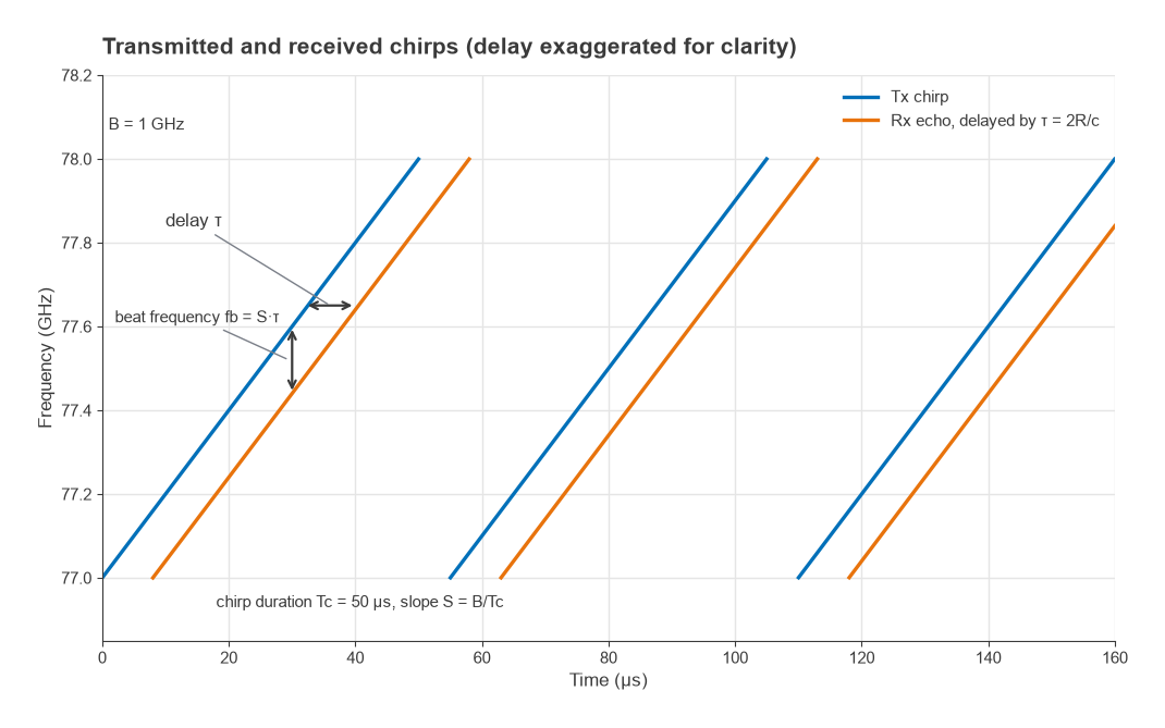
An FMCW radar sweeps its carrier linearly over a bandwidth B during a chirp of duration Tc, so the chirp slope is S = B/Tc. The echo from a target at range R is a copy of the chirp delayed by τ = 2R/c. Mixing the received signal with the transmitted chirp, a process called dechirping, produces a tone at the frequency difference between the two:
fb = Sτ = 2RS/c
Each target therefore produces its own beat frequency, proportional to its range, and an FFT of the sampled beat signal over one chirp gives a range profile. Because the mixer does the heavy lifting, the receiver after the mixer only needs the bandwidth of the beat frequencies, usually a few MHz to a few tens of MHz, rather than the full swept bandwidth. This is the main reason FMCW is attractive for low-cost, low-power sensors.
Velocity from chirp to chirp
A moving target changes range slightly between chirps. The beat frequency hardly changes, but the phase of the beat tone advances by 4πvTc/λ from one chirp to the next, equivalent to a Doppler shift fd = 2v/λ. A second FFT across a frame of N chirps, taken at each range bin, turns that phase progression into velocity. The result is the range-Doppler map used by automotive and industrial radars. The velocity resolution and maximum unambiguous velocity are
Δv = λ/(2NTc) vmax = λ/(4Tc)
Chirp Design: a 77 GHz Worked Example
Consider a radar at 77 GHz (λ = 3.89 mm) that sweeps B = 1 GHz in Tc = 50 µs, with complex (I/Q) sampling of the beat signal at 20 MS/s and frames of N = 128 chirps.
| Quantity | Formula | Result |
|---|---|---|
| Chirp slope | S = B/Tc | 20 MHz/µs |
| Range resolution | c/(2B) | 0.15 m |
| Beat frequency at 50 m | 2RS/c | 6.67 MHz |
| Maximum range (complex IF) | fsc/(2S) | 150 m |
| Doppler at 15 m/s | 2v/λ | 7.71 kHz |
| Maximum unambiguous velocity | λ/(4Tc) | ±19.5 m/s |
| Velocity resolution | λ/(2NTc) | 0.30 m/s |
| Frame time | NTc | 6.4 ms |
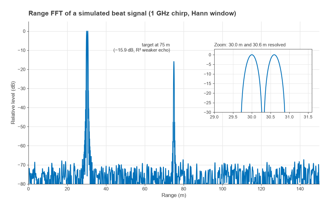
The trade-offs are visible in the table. Wider bandwidth improves range resolution but, for a fixed chirp time, raises the slope and the beat frequency of every target, which consumes IF bandwidth and lowers the maximum range for a given ADC rate. Shorter chirps raise the unambiguous velocity but reduce the energy per chirp. Practical sensors often switch between several chirp profiles to cover short and long range. A simulated range FFT for this chirp, with two targets 0.6 m apart at 30 m and a weaker one at 75 m, shows the 0.15 m bin spacing and how a Hann window widens each peak while suppressing sidelobes.
Worked example: SNR from the radar equation
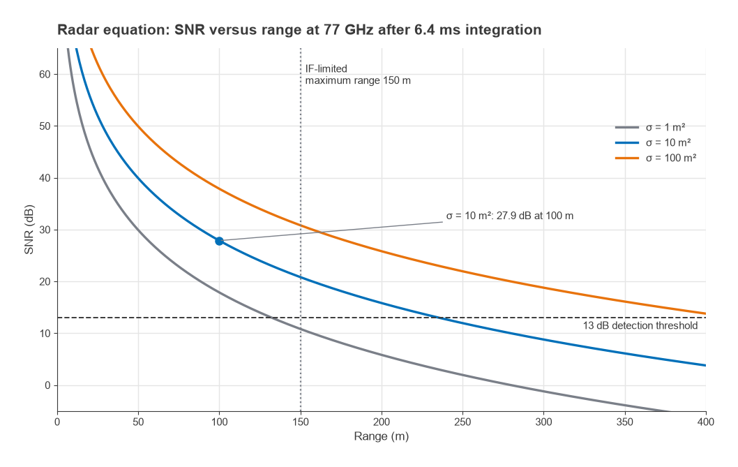
Assume Pt = 12 dBm, Gt = Gr = 15 dBi, a car-sized target with σ = 10 m2 at R = 100 m, a receiver noise figure of 12 dB, 3 dB of losses and coherent integration over the 6.4 ms frame. In decibels:
SNR = −18 dBW + 30 dB (GtGr) − 48.2 dB (λ2) + 10 dB (σ) − 21.9 dB (T) − 33.0 dB ((4π)3) − 80 dB (R4) + 204.0 dB (1/kT0) − 12 dB (F) − 3 dB (L) = 27.9 dB
With a 13 dB detection threshold the same target would be detectable out to about 235 m, but the 20 MS/s IF limits the instrumented range to 150 m, so in this design the IF bandwidth, not the SNR, sets the reach. A 1 m2 target, closer to a pedestrian, reaches the threshold at about 132 m.
FMCW Transceiver Hardware
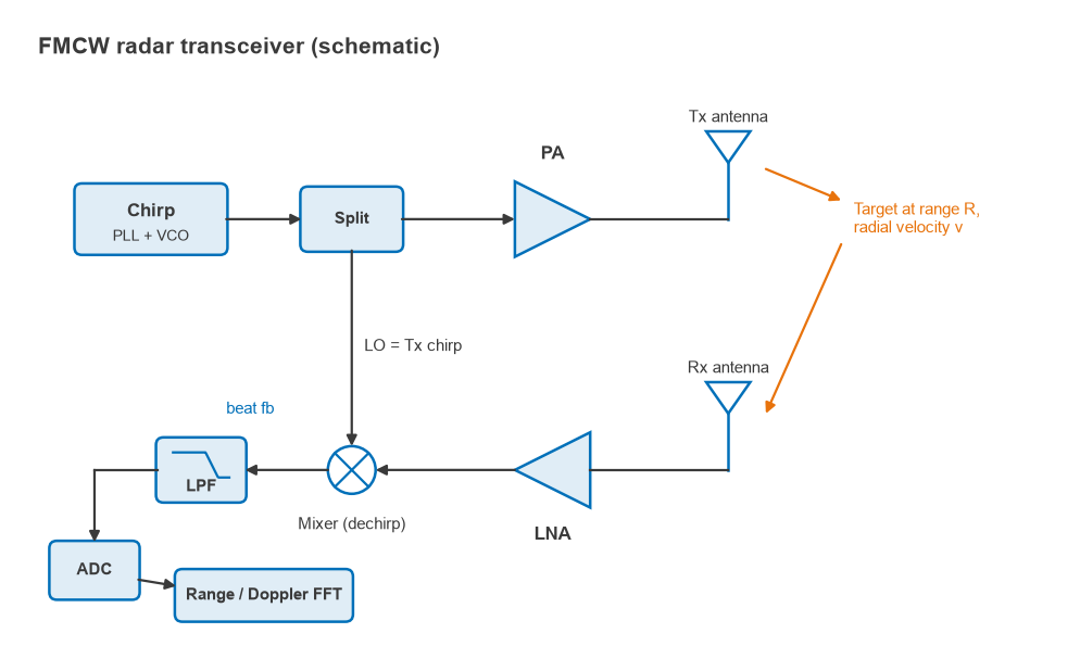
The FMCW signal chain is short. A chirp generator, usually a fractional-N PLL with a ramping divider ratio driving a VCO, produces the sweep; see PLL frequency synthesis and VCO design. Part of the chirp feeds the transmit PA and part becomes the LO for the receive mixer. The receiver is an LNA, a mixer and an IF filter followed by an ADC, which is structurally a zero-IF receiver whose LO happens to be the transmitted signal.
Chirp linearity and phase noise
Any nonlinearity in the sweep makes the beat frequency drift during the chirp, which smears each target across several range bins. Synthesiser settling at the start of each ramp is the usual cause, so the ADC capture window typically excludes the first part of the chirp. Phase noise of the chirp source is partly cancelled for near targets, because the echo and the LO are correlated copies separated by only a short delay; the cancellation weakens as range grows, and strong close reflections such as the bumper or radome can raise the noise floor at longer ranges.
Transmit leakage and multiple antennas
Because FMCW transmits and receives at the same time, leakage from the transmit to the receive antenna appears as a strong beat tone near zero frequency. A high-pass characteristic in the IF chain suppresses it and also partly compensates the R4 fall-off of echo power, since beat frequency rises with range. Modern radar chips use several transmit and receive channels to form a virtual MIMO array for angle estimation, which ties radar to the techniques in MIMO, beamforming and phased arrays and the packaging issues in mmWave radio architectures. The baseband sampling questions are the same as in ADCs and receivers.
Frequently Asked Questions
How does FMCW radar work?
It transmits a linear frequency chirp and mixes each echo with the chirp being transmitted. The echo’s delay turns into a beat frequency proportional to range, fb = 2RS/c, which an FFT resolves. Phase changes across many chirps give velocity.
What sets radar range resolution?
Bandwidth. The resolution is ΔR = c/(2B) for any waveform, so 1 GHz of sweep gives 0.15 m and 4 GHz gives about 3.7 cm. Pulse width, chirp length and sample rate affect other parameters but not this limit.
Why does radar power fall as R to the fourth?
The signal spreads over a sphere on the way to the target and again on the way back, so each leg contributes a 1/R2 factor. Doubling range costs 12 dB of SNR.
What is the difference between pulse and FMCW radar?
Pulse radar transmits short bursts and measures echo delay directly, which suits high power and long range. FMCW transmits continuously at low peak power and measures range as a beat frequency, which suits compact short- and medium-range sensors with low-rate ADCs.
Related Topics
The RF design by application hub links other application areas, including software-defined radio, which is often used for radar experiments. For the underlying receiver theory see thermal noise and kTB and antennas and propagation for radio design. Terms are defined in the wireless terms glossary.