


Electromagnetic waves are coupled oscillating electric and magnetic fields that carry energy through space at the speed of light, with no medium required. Their main properties are frequency and wavelength, field strength and power density, wave impedance, polarization, and the way they reflect, refract, diffract and are absorbed. For an RF engineer, these properties explain how an antenna launches a signal, how far it goes and what happens to it on the way.
Radio waves differ from light only in frequency, so the same physics applies across the spectrum. This article concentrates on the properties that matter in RF work, with a worked field-strength calculation and a reflection example.
How an Electromagnetic Wave Is Formed
A changing electric field produces a magnetic field, and a changing magnetic field produces an electric field. Maxwell’s equations show that this pair can sustain itself and travel away from its source. An accelerating charge, such as the current in an antenna, starts the process.
Far from an antenna the wave is approximately a plane wave. Its electric field E and magnetic field H are perpendicular to each other and to the direction of travel, and they are in phase. This is a transverse electromagnetic (TEM) wave. The same field pattern exists inside a coaxial cable, which is why a TEM line and a free-space wave share so many properties.
Close to an antenna the fields are more complicated, with stored reactive energy. The plane-wave results below apply in the far field, generally taken as beyond about 2D2/λ for an antenna of largest dimension D, and also several wavelengths away from small antennas.
Speed, Frequency and Wavelength
In vacuum all electromagnetic waves travel at c = 1/√(μ0ε0) = 299,792,458 m/s. Speed, frequency and wavelength are linked by c = fλ, as covered in the relationship between frequency and wavelength. In a non-magnetic dielectric the speed falls to c/√εr.
The electromagnetic spectrum runs from radio waves through infrared, visible light and ultraviolet to X-rays and gamma rays. The radio part is split into frequency bands with their own propagation behaviour. Radio photons carry far too little energy to ionize atoms, which is the main difference between this end of the spectrum and the far end.
Wave Impedance and Power Density
The ratio of E to H in a plane wave is a property of the medium, the wave impedance:
η = √(μ/ε), which in free space gives η0 ≈ 376.7 Ω
In a non-magnetic dielectric it becomes η0/√εr. This is the same idea as the characteristic impedance of a line, and it explains why a wave reflects at a change of material, just as a signal reflects at a mismatch on a line.
Power flows in the direction of the Poynting vector, and the average power density is S = ErmsHrms = Erms2/η. Far from a source, the power spreads over a sphere of area 4πr2, so power density falls with the square of distance and field strength falls with distance itself:
S = EIRP / (4πr2)
This inverse-square spreading is the basis of free-space path loss. It is not absorption. No energy is lost; it is simply spread over a larger area.
Worked Example: Field Strength at 100 m
A transmitter has an EIRP of 10 W. What are the power density and the field strengths in free space at 100 m?
S = 10 / (4π × 1002) = 79.6 µW/m2
Erms = √(S × 376.7) = 0.173 V/m, which is a peak value of 0.245 V/m
Hrms = Erms / 376.7 = 0.460 mA/m
As a check, Erms × Hrms returns 79.6 µW/m2. Doubling the distance to 200 m would halve both field strengths and divide the power density by four.
Polarization
Polarization is the orientation of the electric field as the wave travels. If E stays along one line the wave is linearly polarized, and it is usually described as vertical or horizontal. If E rotates, the wave is circularly or elliptically polarized, with right-hand or left-hand sense.
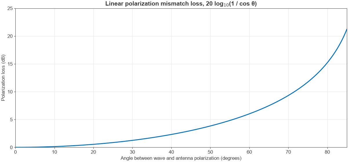
An antenna receives best when its polarization matches the wave. For two linearly polarized antennas misaligned by an angle θ, the power falls by cos2θ. Figure 1 plots the loss:
- 30° misalignment: 1.25 dB
- 45° misalignment: 3.01 dB
- 80° misalignment: 15.2 dB
In theory the loss is infinite at 90°, but real cross-polarization and reflections set a practical limit, often in the range of 20 dB to 30 dB. A linear antenna receiving a circular wave loses 3 dB at any angle, and this is why satellite links with unknown orientation use circular polarization. The antenna parameters page covers this along with gain and beamwidth.
Reflection and Refraction at a Boundary
At the boundary between two materials, part of the wave reflects and part continues into the second material with a changed direction. The angles obey the law of reflection and Snell’s law, n1 sin θ1 = n2 sin θ2, where the refractive index is n = √εr for a non-magnetic material.
Worked Example: Normal Incidence on a Dielectric
A wave in air strikes a smooth, lossless dielectric with εr = 5, a rough value for dry masonry, at normal incidence. Using the wave impedance mismatch:
Γ = (1 – √5) / (1 + √5) = -0.382
Reflected power is Γ2 = 14.6%, so the transmitted power is 85.4%, a loss of 0.68 dB at the first surface. The negative sign means the electric field reverses on reflection. A real wall has two faces and some loss, so the true figure depends on its thickness and frequency.
The Effect of Angle and Polarization
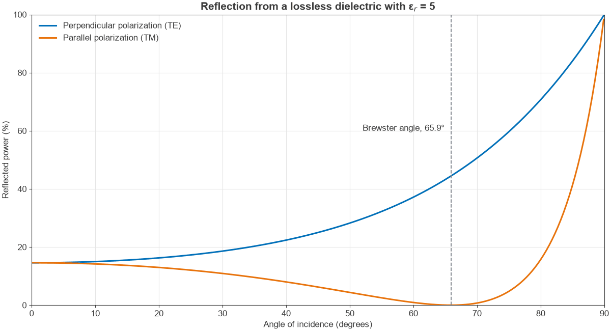
Away from normal incidence, the Fresnel equations show that reflection depends on polarization. Figure 2 compares the two cases. With the electric field in the plane of incidence, reflection falls to zero at the Brewster angle, θB = arctan(√εr) = 65.9° for this material. With the field perpendicular to that plane, reflection only ever rises. At grazing incidence, both reach nearly 100%, which is why ground reflections matter so much on long, low paths.
Absorption, Conductors and Skin Depth
In a lossy material the wave decays exponentially, turning its energy into heat. Water molecules, for instance, absorb strongly at microwave frequencies, and building materials absorb more as frequency rises.
A good conductor does something different. It reflects nearly all of the wave, and the small part that enters decays within a very short distance, the skin depth:
δ = √(1 / (π f μ σ))
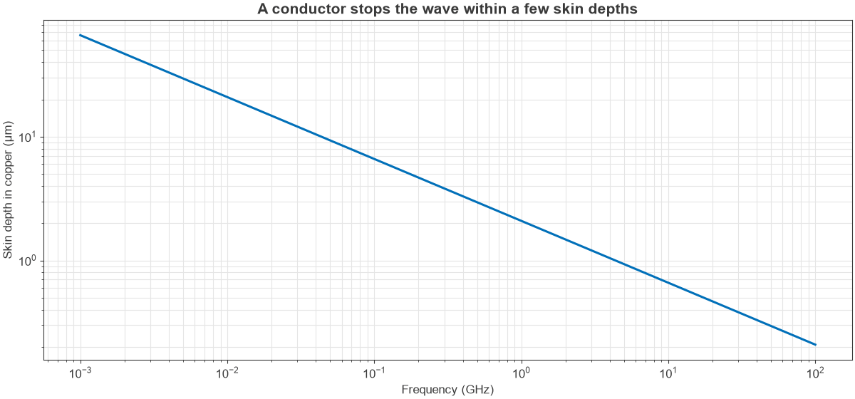
For copper this is about 6.6 µm at 100 MHz, 2.1 µm at 1 GHz and 0.66 µm at 10 GHz, as Figure 3 shows. A thin metal layer therefore works well as a shield, provided that it has no gaps. Metals do not transmit radio waves, and RF shielding cans rely on this. The same effect confines RF current to the surface of a conductor and raises its loss, as described on the skin effect page.
Diffraction, Scattering and Dispersion
Waves bend around obstacles, a property called diffraction. The effect is strongest when the obstacle is not large compared with the wavelength, so low-frequency signals reach behind hills and buildings better than millimeter waves. Rough surfaces and small objects scatter energy in many directions, and in an urban or indoor channel the result is multipath, where several copies of a signal arrive with different delays and phases and can cancel. The antennas and propagation hub looks at these channel effects.
Dispersion means that speed depends on frequency. It is the reason a prism spreads white light, and in RF it appears in the ionosphere, in waveguides and to a lesser degree in microstrip. A modulated signal then has two relevant speeds: the phase velocity of the carrier and the group velocity of the envelope. Wideband signals in a dispersive path spread out in time.
Frequently Asked Questions
What are the main properties of electromagnetic waves?
The main properties are frequency, wavelength, speed, amplitude, polarization and wave impedance. They also reflect, refract, diffract, scatter and are absorbed, and all of these depend on frequency and on the materials involved.
Do electromagnetic waves need a medium?
No. The electric and magnetic fields sustain each other, so these waves travel through vacuum. A material only changes the speed and may absorb or reflect the wave.
Why are the electric and magnetic fields perpendicular?
In a plane wave, Maxwell’s equations require E, H and the direction of travel to be mutually perpendicular. Their magnitudes are also linked by the wave impedance, about 377 Ω in free space.
What is the difference between reflection and absorption?
Reflection sends the energy back into the first medium, while absorption converts it to heat inside the material. A metal surface mostly reflects, and a lossy material such as wet concrete does more of the absorbing.
Related Topics
These ideas lead into antennas and propagation and the RF fundamentals hub. To see how a wave’s energy is measured, read understanding power in RF systems.