


Frequency bands in RF design are named ranges of the radio spectrum, set out by the ITU, by the IEEE letter system and by national regulators. The band fixes the wavelength, and so it sets antenna size, path loss, available bandwidth, component choice and the rules for transmitting. Choosing a band is often the first system decision in an RF design, because almost everything else depends on it.
Several overlapping naming systems are in use, and a designer needs to know all of them. This article summarises those systems, explains how propagation and bandwidth change across the spectrum, and shows with a worked example why “higher frequencies have more path loss” is only half of the story.
How the Radio Spectrum Is Divided
ITU Frequency Bands
The International Telecommunication Union divides the radio spectrum into decade-wide bands. Each covers a factor of ten in frequency and a corresponding range of wavelength.
| Band | Frequency range | Wavelength | Typical uses |
|---|---|---|---|
| VLF | 3 kHz to 30 kHz | 100 km to 10 km | Submarine communication, navigation |
| LF | 30 kHz to 300 kHz | 10 km to 1 km | Time signals, low-frequency RFID |
| MF | 300 kHz to 3 MHz | 1 km to 100 m | AM broadcasting |
| HF | 3 MHz to 30 MHz | 100 m to 10 m | Shortwave, amateur radio, aviation |
| VHF | 30 MHz to 300 MHz | 10 m to 1 m | FM broadcasting, air band |
| UHF | 300 MHz to 3 GHz | 1 m to 100 mm | Cellular, Wi-Fi, GNSS |
| SHF | 3 GHz to 30 GHz | 100 mm to 10 mm | Radar, satellite, 5G, Wi-Fi |
| EHF | 30 GHz to 300 GHz | 10 mm to 1 mm | Millimeter-wave links, automotive radar |
IEEE Letter Bands
Radar and microwave engineers use the letter bands, which started with wartime radar and were later standardised by the IEEE. Boundaries can differ slightly between sources, but these values are the usual ones.
| Letter | Frequency range | Letter | Frequency range |
|---|---|---|---|
| L | 1 GHz to 2 GHz | K | 18 GHz to 27 GHz |
| S | 2 GHz to 4 GHz | Ka | 27 GHz to 40 GHz |
| C | 4 GHz to 8 GHz | V | 40 GHz to 75 GHz |
| X | 8 GHz to 12 GHz | W | 75 GHz to 110 GHz |
| Ku | 12 GHz to 18 GHz | mm | 110 GHz to 300 GHz |
ISM and Unlicensed Bands
The Industrial, Scientific and Medical bands were set aside for equipment such as RF heaters. Radio communication may also use them on a shared, unlicensed basis, subject to power and duty limits, and must accept interference from other users. Common ISM bands include 13.56 MHz, 433.05 MHz to 434.79 MHz (ITU Region 1), 902 MHz to 928 MHz (Region 2), 2.4 GHz to 2.5 GHz and 5.725 GHz to 5.875 GHz.
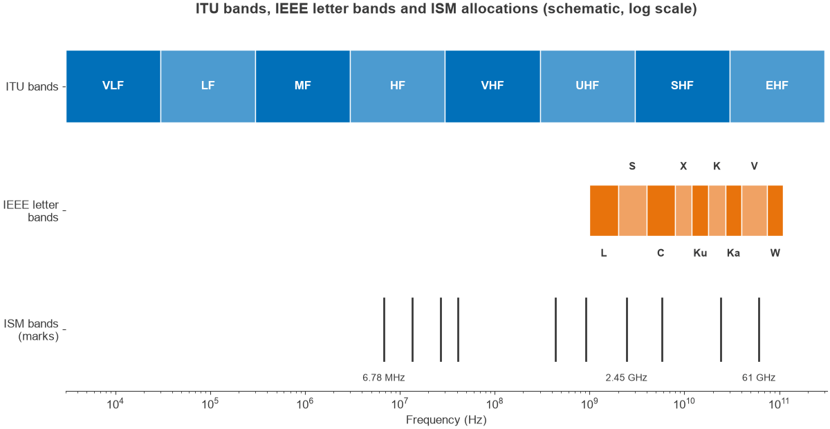
These allocations are not fully global. The 915 MHz band is available in the Americas, while Europe uses a separate short-range device band around 868 MHz, and limits vary by country. Check the current local regulations before fixing a design, and treat any summary of limits, including this one, as approximate. Figure 1 places all three systems on one axis.
How Band Choice Affects Propagation
Lower frequencies generally travel further around obstacles and pass through materials more easily. HF signals can refract from the ionosphere and cover intercontinental paths. VHF and UHF signals travel by line of sight, with some diffraction and reflection, and they get through walls with moderate loss.
Above a few gigahertz, building penetration falls away and paths become closer to optical. Rain attenuation becomes significant above about 10 GHz. Atmospheric gases add absorption peaks too, the best known being the oxygen line near 60 GHz, where attenuation is roughly 15 dB/km. In that band the loss limits range, and it can also be useful, since it reduces interference between neighbouring links. The properties of electromagnetic waves explain the mechanisms involved.
Bandwidth and Capacity
Channel capacity grows with bandwidth, and bandwidth is what the upper bands offer. A fractional bandwidth of a few percent is manageable for filters and antennas, and at a higher carrier that same percentage contains far more hertz. Compare these examples, which use typical allocations:
- The 2.4 GHz band as used by Wi-Fi and Bluetooth, 2400 MHz to 2483.5 MHz, offers 83.5 MHz, or 3.4% of its centre frequency.
- An 800 MHz millimeter-wave block at 28 GHz is only 2.9%, about the same fractional width with almost ten times the absolute bandwidth.
- A 7 GHz block around 60 GHz is 11.7%, which is wide but still possible to work with.
The fractional width of a band also controls how hard the RF design is. It is the reason 5G front ends face such a difficult filtering problem below 6 GHz, with many closely spaced bands, while millimeter-wave radios have wide channels but difficult power and loss budgets.
Worked Example: Is 3.5 GHz Worse Than 900 MHz?
Compare a 2 km line-of-sight link at 900 MHz and at 3.5 GHz. The result depends on what is held constant.
Case 1: Fixed Antenna Gain
With isotropic or fixed-gain antennas, free-space path loss is FSPL = 20 log10(4πdf/c):
- 900 MHz: 97.6 dB
- 3.5 GHz: 109.3 dB
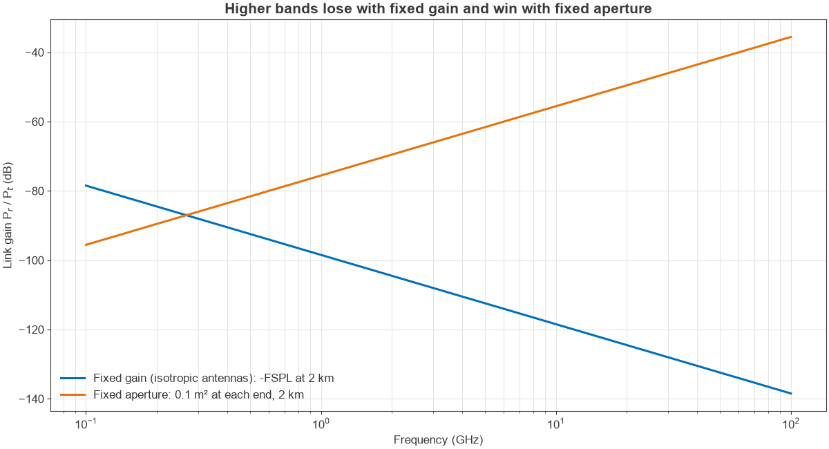
The higher band loses 11.8 dB, which is 20 log10(3500/900). This is the source of the common saying. The physics is not that the air absorbs more; a fixed-gain antenna has an effective aperture A = Gλ2/4π, so it captures less power at a shorter wavelength.
Case 2: Fixed Antenna Size
Now hold the physical aperture at 0.1 m2 at each end. A wavelength of 333 mm at 900 MHz gives a gain of 10.5 dBi, while 85.7 mm at 3.5 GHz gives 22.3 dBi. Using the Friis form with both apertures:
Pr/Pt = AtAr / (λ2d2)
- 900 MHz: -76.5 dB
- 3.5 GHz: -64.7 dB
The higher band now wins by the same 11.8 dB. Two antennas of fixed size gain 11.8 dB each over the fixed-gain case, and one of those cancels the extra path loss. Figure 2 shows both trends. In practice, the narrower beam of the higher-gain antenna has to be pointed, which is why millimeter-wave systems use phased arrays. Foliage and walls can still take away the advantage, so this is a free-space comparison only.
Choosing a Frequency Band
Band selection is a trade across several factors, and regulation often settles it first. Work through these questions in roughly this order:
- Regulation: is the band licensed, shared or unlicensed where the product will be sold, and what are the limits on power and duty cycle?
- Range and environment: does the signal need to get through walls or terrain, or is the path clear?
- Data rate: how much bandwidth is needed, and is it available in one channel?
- Antenna size: does the wavelength allow an efficient antenna in the available space? A small product at a low frequency will often have poor antenna efficiency.
- Component availability: filters, amplifiers and modules are cheap in high-volume bands and costly elsewhere.
- Interference: crowded bands such as 2.4 GHz raise the noise and interference level, and coexistence with other radios in a product needs planning.
- Power: low-frequency amplifiers are more efficient, and device gain falls toward the top of a transistor’s range.
A link budget converts these choices into numbers, and it should be done early, for each candidate band.
Frequently Asked Questions
What are the main RF frequency bands?
The ITU bands VLF to EHF cover 3 kHz to 300 GHz in decade steps. In microwave work the IEEE letter bands L, S, C, X, Ku, K, Ka, V and W are common. Cellular, Wi-Fi and ISM allocations are narrower ranges inside these.
Do higher frequencies travel less far?
With fixed-gain antennas, path loss rises with frequency, and penetration through obstacles usually gets worse. With a fixed antenna size, however, a higher frequency provides more gain and can give a stronger free-space link, provided the beams are aligned.
What is the difference between licensed and unlicensed bands?
A licensed band gives its holder protected use of the spectrum, often at a high cost. An unlicensed band such as 2.4 GHz is open to any compliant device, without protection from interference.
Can the ISM bands be used everywhere?
Not all of them. The 2.4 GHz band is available almost worldwide, but the 433 MHz and 915 MHz bands depend on the region. Rules also differ by country, so compliance has to be checked for each market.
Related Topics
See the relationship between frequency and wavelength, the RF fundamentals hub and antennas and propagation. The radio architectures series shows how band choices shape a complete radio.