

A double-balanced mixer is a frequency converter in which both the LO and the RF ports are driven through balanced circuits, usually two baluns feeding a ring of four diodes or transistors, so that the LO and RF signals cancel at the output and only their mixing products remain. Mixer topologies differ mainly in how many ports are balanced, which sets isolation, spurious suppression, conversion loss and linearity.
Every mixer multiplies an RF signal by a local oscillator to produce sum and difference frequencies. In practice the multiplication is almost always done by switching: the LO turns devices fully on and off, and the RF signal is steered alternately to the output with opposite polarity. This page compares single-ended, single-balanced, double-balanced, triple-balanced and Gilbert cell mixers on isolation, conversion loss or gain, LO drive and IP3, with the arithmetic behind each figure. It is part of the RF mixers section of the RF design reference, and the receiver context is set out in Radio Architectures, Part 2: receivers, LOs and mixers.
The switching model of a mixer
Treat the LO as a square wave s(t) that switches between +1 and −1. Its Fourier series contains only odd harmonics:
s(t) = (4/π) [cos ωLOt − (1/3) cos 3ωLOt + (1/5) cos 5ωLOt − …]
Multiplying an RF tone A cos ωRFt by the fundamental term gives two products, at ωLO − ωRF and ωLO + ωRF, each with amplitude (2/π)A. The wanted IF therefore sits 20log(π/2) = 3.92 dB below the RF input. That 3.92 dB is the conversion loss of an ideal lossless double-balanced switching mixer; the missing power has gone into the unwanted sideband and into products with the LO harmonics, at 3ωLO ± ωRF (13.5 dB down) and 5ωLO ± ωRF (17.9 dB down). Diode resistance, balun loss and mismatch raise practical figures to about 5.5 to 7.5 dB.
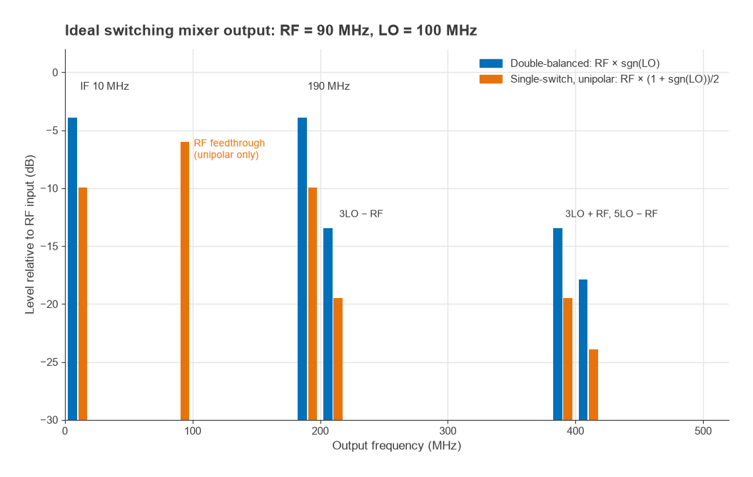
If the switching is unipolar, between 1 and 0 rather than +1 and −1, the switching function gains a DC term of 1/2 and its fundamental halves. The IF drops to 9.94 dB below the RF input, and the RF signal appears directly at the output, only 6.0 dB down. This is the basic weakness of an unbalanced mixer: its own input signals leak through. Balancing a port is the way to cancel that leakage by symmetry rather than by filtering.
Single-ended and single-balanced mixers
A single-ended mixer uses one diode or one transistor, with the RF and LO combined at its input and the IF taken off through a filter. It is the cheapest form and still appears at millimetre-wave frequencies, where baluns are difficult. All three signals appear at all three ports, so isolation depends entirely on filtering, which only works if the RF, LO and IF bands are well separated.
A single-balanced mixer uses two diodes and one balun, usually on the LO port. The two diodes conduct on opposite half cycles of the LO, so the LO currents cancel at the RF and IF ports, giving typically 20 to 30 dB of LO isolation. The RF port is not balanced, so RF-to-IF feedthrough remains and must be filtered. Even-order products involving the balanced port are also suppressed. Single-balanced designs need less LO power than a full ring and are common in integrated receivers.
The double-balanced mixer
The classic double-balanced mixer (DBM) is a ring, or quad, of four matched Schottky diodes with a balun on the LO port and a balun on the RF port. The IF is taken from the centre tap of one balun. On one half of the LO cycle one pair of diodes conducts and connects the RF balun to the IF with one polarity; on the other half the other pair conducts and reverses the polarity. The RF signal is therefore multiplied by a ±1 square wave, which is exactly the ideal switching model above.
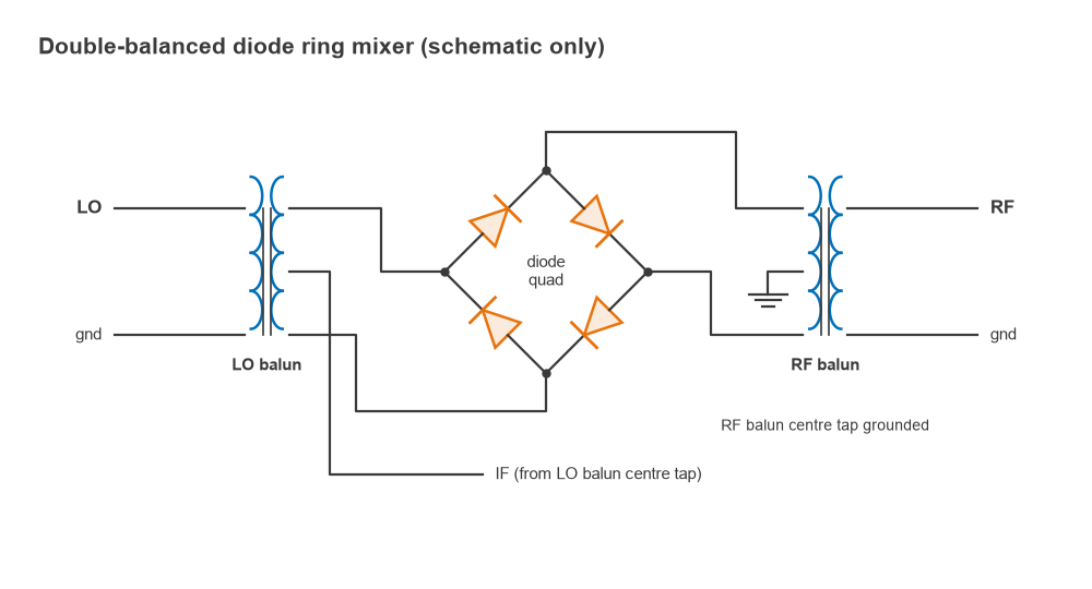
Because both the LO and the RF ports are balanced, neither signal appears at the IF in an ideal ring, and the LO is isolated from the RF port. In practice, diode mismatch and balun imbalance limit isolation to typically 30 to 50 dB at low frequencies, falling as frequency rises and the baluns degrade. Every product with an even LO harmonic or an even RF harmonic is also suppressed, which removes many of the spurs in a frequency plan. The balun itself is the component that most often limits bandwidth; balun types are covered in RF baluns.
Diode DBMs are graded by LO drive level. A “level 7” mixer expects about +7 dBm of LO; higher-level types use more diodes in series per arm and expect +13, +17 or +23 dBm. More LO drive keeps the diodes switched hard even when a large RF signal is present, so input IP3 rises roughly in step with LO power. A common rule of thumb is that a diode DBM’s input IP3 sits about 5 to 10 dB above its LO drive.
Triple-balanced mixers
A triple-balanced mixer uses two diode rings and baluns on all three ports, including the IF. With the IF also balanced and isolated through its own transformer, the IF band no longer needs to be separate from the RF and LO bands, and the IF port can be very wide, sometimes overlapping the RF range. Triple-balanced mixers usually need more LO power, often +10 to +20 dBm, and in return give higher IP3 and better spur suppression than a single ring. They suit broadband converters where the frequency plan cannot keep the IF away from the RF.
Active mixers and the Gilbert cell
The Gilbert cell is a double-balanced active mixer. A differential pair converts the RF voltage into a differential current, and four cross-connected switching transistors, driven by the LO, commutate that current between two load resistors. The structure is double-balanced, like the diode ring, but it provides gain rather than loss. With a transconductor of gm and load resistance RL, the voltage conversion gain is
Gc = (2/π) × gm × RL
For gm = 10 mS and RL = 400 Ω, Gc = 0.637 × 10 mS × 400 Ω = 2.55, or 8.1 dB. The LO only has to switch the upper quad, which needs a few hundred millivolts, so typical LO drive is about −10 to 0 dBm. The cell integrates easily and is the usual mixer in RFICs.
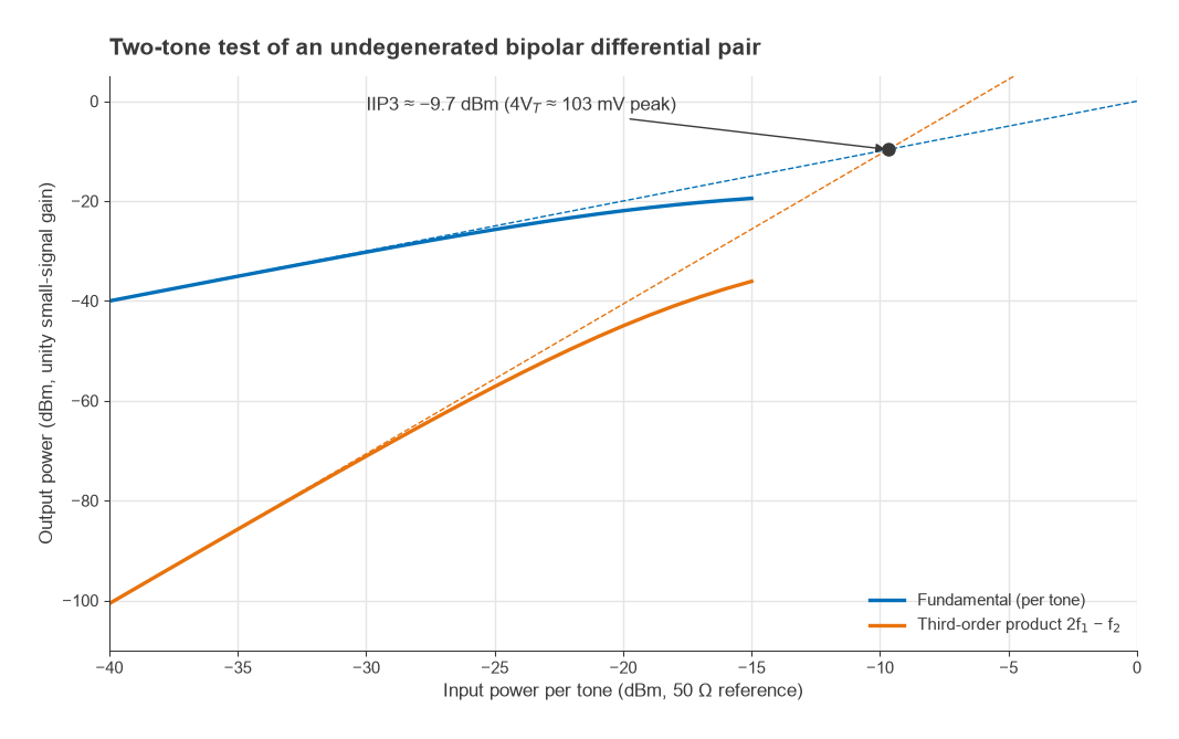
The price is linearity and noise. An undegenerated bipolar differential pair has a tanh transfer characteristic, Iout = IEE tanh(Vin/2VT). Expanding the tanh to third order gives an input-referred third-order intercept amplitude of exactly 4VT, about 103 mV peak at room temperature. Referred to 50 Ω, that is only about −9.7 dBm. Degeneration or a more linear transconductor raises IP3 at the expense of gain, so practical Gilbert cells commonly reach about 0 to +10 dBm. Noise figure is typically higher than the conversion loss of a passive mixer, often 8 to 15 dB, because the transconductor and the switching quad both add noise.
Mixer comparison: isolation, conversion loss, LO drive and IP3
The table gives typical approximate ranges as of 2026 for discrete and integrated mixers below a few gigahertz, drawn from the general behaviour of each topology rather than any specific product. Isolation in particular falls as frequency increases.
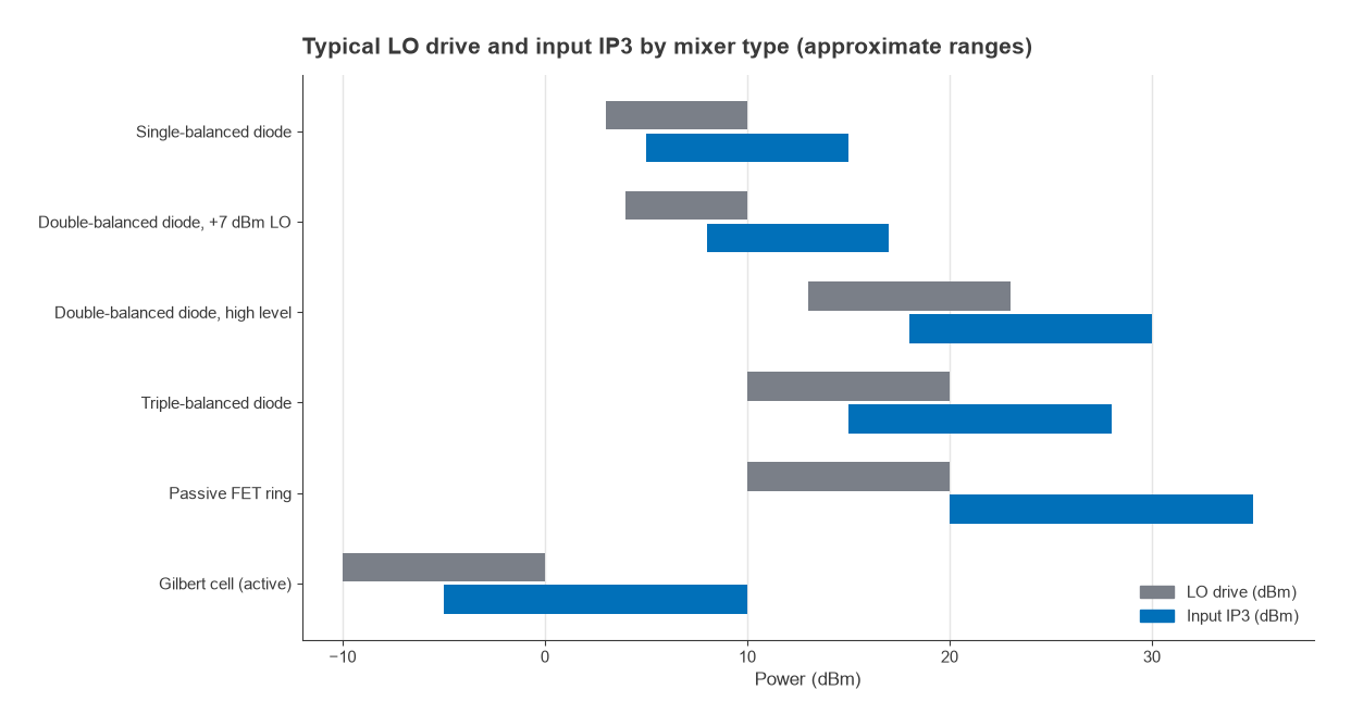
| Topology | Switching devices | LO-to-RF isolation | LO-to-IF isolation | Conversion loss or gain | LO drive | Input IP3 |
|---|---|---|---|---|---|---|
| Single-ended | 1 diode or FET | Low, set by filtering | Low, set by filtering | About 6 to 9 dB loss | About 0 to +7 dBm | About 0 to +10 dBm |
| Single-balanced | 2 diodes or FETs | About 20 to 30 dB | About 15 to 25 dB | About 5.5 to 8 dB loss | About +3 to +10 dBm | About +5 to +15 dBm |
| Double-balanced diode ring | 4 diodes | About 30 to 50 dB | About 25 to 45 dB | About 5.5 to 7.5 dB loss | +7 dBm (level 7) up to +23 dBm | About +8 to +30 dBm, depending on level |
| Triple-balanced | 8 diodes | About 30 to 45 dB | About 25 to 40 dB | About 6 to 8 dB loss | About +10 to +20 dBm | About +15 to +28 dBm |
| Gilbert cell (active) | 4 switching transistors plus a differential pair | About 30 to 50 dB on chip | About 20 to 40 dB | About 0 to +15 dB gain | About −10 to 0 dBm | About −5 to +10 dBm |
Worked example: intermodulation and LO leakage
Two equal tones at −10 dBm each reach a mixer. For a passive DBM with 6.5 dB conversion loss and an input IP3 of +15 dBm, the input-referred third-order product is
PIM3,in = 3Pin − 2·IIP3 = 3(−10) − 2(15) = −60 dBm
At the IF the wanted tones are at −16.5 dBm and the IM3 products at −66.5 dBm, so the intermodulation ratio is 50 dBc. A Gilbert cell with 10 dB gain and an input IP3 of +5 dBm gives PIM3,in = −30 − 10 = −40 dBm; its IF tones are at 0 dBm and IM3 at −30 dBm, a ratio of only 30 dBc. The 10 dB difference in IIP3 becomes 20 dB in the intermodulation ratio because IM3 rises 3 dB for every 1 dB of input. The same arithmetic is used across a whole receiver in cascaded IP3, and the background is in intermodulation and intercept points.
Isolation matters in a similar way. A level 7 DBM driven at +7 dBm with 40 dB of LO-to-RF isolation puts −33 dBm of LO back onto its RF port. In a receiver, that leakage passes backward through the LNA’s reverse isolation towards the antenna, and in a zero-IF receiver it also self-mixes to produce a DC offset.
Passive vs active mixers
Passive mixers, whether diode rings or FET rings switched by the LO, have conversion loss, a noise figure close to that loss, and high IP3, at the cost of substantial LO power. Passive FET ring mixers can reach very high IP3 because a well-driven FET channel is close to an ideal switch. Active mixers have gain, need little LO power and integrate well, but have lower IP3 and higher noise figure. The trade is a system decision that also depends on the image rejection scheme and on whether the design needs the quadrature outputs of an IQ demodulator.
Frequently asked questions
What is a double-balanced mixer?
It is a mixer in which both the LO and RF ports are balanced, typically with a ring of four diodes and two baluns. The symmetry cancels the LO and RF signals at the IF port and suppresses even-order spurious products, giving good port isolation and a cleaner output spectrum than single-ended or single-balanced designs.
Passive vs active mixer: which should I use?
Use a passive mixer when linearity and dynamic range matter most and LO power is available, as in base stations and test equipment. Use an active mixer when gain, low LO power and integration matter more, as in most RFIC receivers. Check the full cascade: a passive mixer’s loss adds to noise figure, while an active mixer’s lower IP3 can limit blocking performance.
Why is the conversion loss of a diode mixer about 6 dB?
An ideal switching mixer already loses 3.92 dB, because half the converted power goes to the unwanted sideband and some goes to LO harmonic products. Diode on-resistance, balun loss and port mismatch add roughly another 2 to 3 dB in practical designs.
Related topics
The mixer’s place in the receiver noise budget is covered in cascaded noise figure, and the oscillator that drives it in PLL frequency synthesis. The full set of mixer topics is collected in the RF mixers hub, and short definitions are in the wireless terms glossary.