

A low-IF receiver is a quadrature downconversion receiver architecture that translates the wanted channel to a small, non-zero intermediate frequency, typically between about half and a few times the channel bandwidth, instead of to DC. It keeps most of the integration advantages of a zero-IF receiver while moving the signal away from DC offsets and flicker noise, at the cost of an image that falls only one or two channels away and must be rejected by I/Q balance and complex (polyphase) filtering rather than by an RF filter.
Low-IF is common in narrowband integrated transceivers, such as short-range and low-power radios, where a fully integrated front end matters more than the last few decibels of image rejection. This page explains how the architecture works, why its image is harder to handle than in a superheterodyne, how polyphase filters provide image rejection, and how to budget I/Q mismatch. It is part of the radio architectures series in the RF design guide.
How a Low-IF Receiver Works
The front end is the same as in any receiver: a band-select filter and a low noise amplifier, as described in Part 1 and Part 2 of the series. The signal then drives two mixers whose local oscillators are 90° apart, producing in-phase (I) and quadrature (Q) outputs. The LO is set to fLO = fRF − fIF, so the wanted channel lands at +fIF in the complex signal I + jQ.
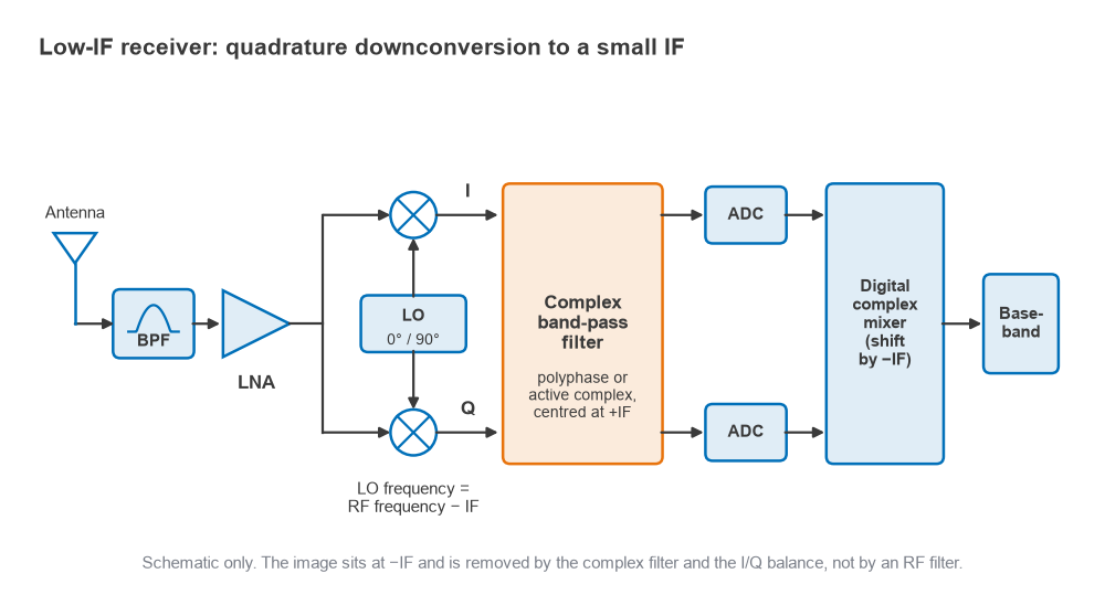
Because the I and Q paths together carry a complex signal, positive and negative frequencies are distinct. A signal at fRF appears at +fIF; a signal at the image frequency fim = fLO − fIF = fRF − 2fIF appears at −fIF. After a complex channel filter centred on +fIF, the ADCs digitize I and Q, and a digital complex mixer shifts the channel the last step from fIF to DC. The ADC must therefore cover fIF plus half the channel bandwidth, rather than only half the channel bandwidth as in zero-IF.
The Image Problem Compared With Zero-IF and Superheterodyne
In a superheterodyne with a high IF, the image is 2fIF away from the wanted signal, often tens or hundreds of megahertz, and a fixed RF filter removes it (see image frequency and image-reject mixers). In a low-IF receiver 2fIF is only a few megahertz or less, so the image is a nearby channel inside the band-select filter’s passband. No practical RF filter can separate the two.
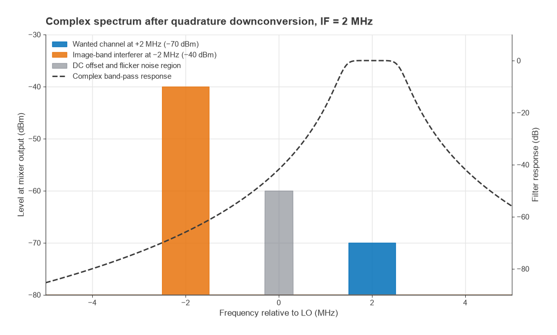
A zero-IF receiver has no separate image: the image of the channel is the channel itself, mirrored about DC. Quadrature imbalance there causes self-interference within the channel, which degrades EVM but scales with the signal. Low-IF trades that for a true external image, a different channel that may be much stronger than the wanted one. In return, the wanted signal sits away from DC, so DC offsets, LO self-mixing products, second-order intermodulation products near DC and 1/f noise can be removed by a high-pass or band-pass response without cutting into the channel.
| Property | Superheterodyne | Low-IF | Zero-IF |
|---|---|---|---|
| Image location | 2fIF away, far out | 2fIF away, adjacent or nearby channel | Mirror of the channel itself |
| Image removed by | RF or IF filter | I/Q balance and complex filtering | I/Q balance (affects EVM) |
| DC offset and 1/f noise | Not an issue | Outside the channel | Inside the channel |
| Off-chip filters | Usually needed | Few | Few |
| ADC bandwidth | Depends on IF | fIF + BW/2 | BW/2 |
A broader comparison of these choices is in superheterodyne vs zero-IF vs direct sampling.
Complex Signals and the Polyphase Filter
A real filter has a response that is symmetric about zero frequency, so it cannot pass +fIF and reject −fIF. A complex filter operates on the I and Q signals together and can be asymmetric. The usual construction takes a low-pass prototype HLP(jω) and shifts it in frequency, H(jω) = HLP(j(ω − ωIF)). In an active implementation each integrator is cross-coupled between the I and Q paths with a gain set by ωIF, which moves the poles off the real axis.
Passive RC polyphase filters
The passive RC polyphase filter is a ring of resistors and capacitors driven by four phases (I, Q, −I, −Q). With ideal quadrature inputs, one stage with time constant RC passes the two sequences with gains
H+ = (1 + ωRC)/(1 + jωRC) and H− = (1 − ωRC)/(1 + jωRC)
so the image rejection of one stage is [(1 + x)/(1 − x)]2, with x = ω/ωp and ωp = 1/RC. The rejection is infinite at the pole frequency and falls off on either side. Cascading stages with staggered poles multiplies their rejections and widens the band. With R = 1 kΩ, a pole at 2 MHz needs C = 1/(2π × 2 MHz × 1 kΩ) = 79.6 pF.
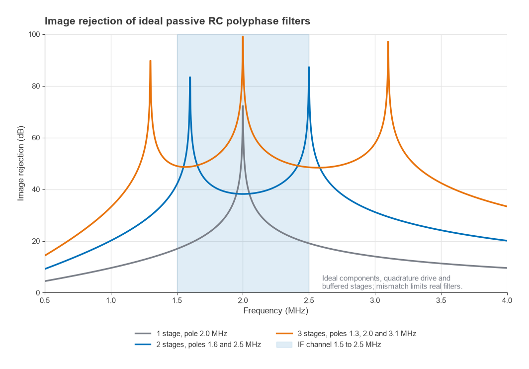
These ideal figures assume perfect components and stages that do not load each other. In practice each passive stage attenuates the wanted signal, typically by about 3 dB once loading is included, and the achievable rejection is set by resistor and capacitor matching, not by the ideal response. Integrated polyphase filters are commonly quoted at around 30 to 50 dB of image rejection, depending on matching and layout.
Image Rejection and I/Q Mismatch
Whatever the filter, the I and Q paths before it must be balanced. If the Q path has a relative gain ε (as an amplitude ratio) and a phase error φ from 90°, the image rejection ratio of the quadrature downconverter is
IRR = (1 + 2ε cos φ + ε2) / (1 − 2ε cos φ + ε2)
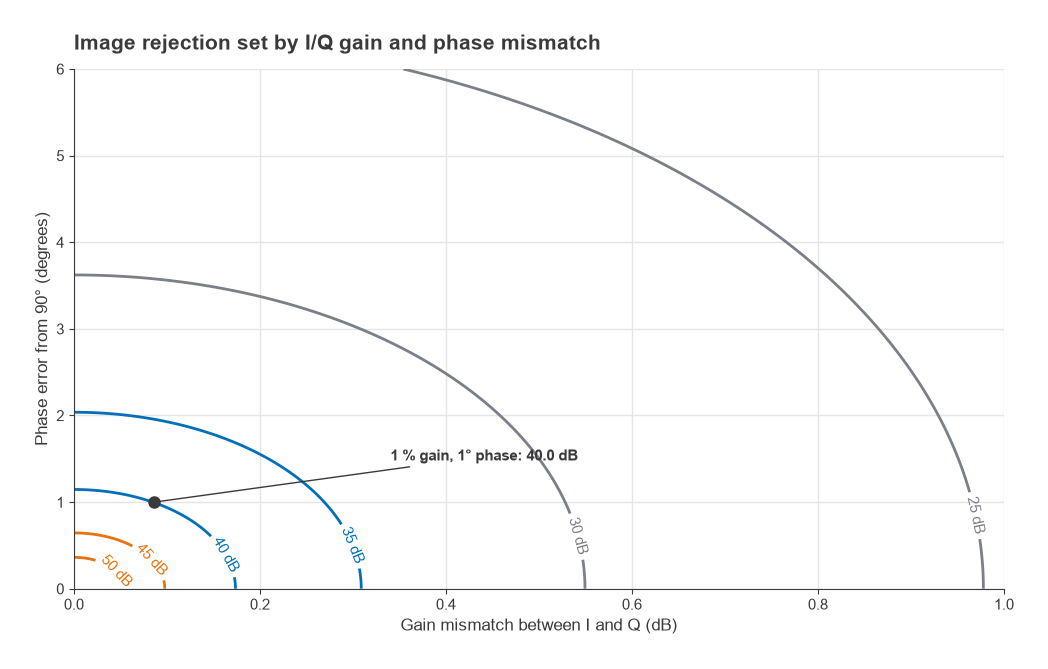
For small errors this reduces to IRR ≈ 4/(Δ2 + φ2), where Δ = ε − 1 is the fractional gain error and φ is in radians. A 1 percent gain error and a 1° phase error give 4/(0.0001 + 0.000305) ≈ 9,890, or 40.0 dB. Phase error alone of 1° limits the IRR to 41.2 dB, and gain error alone of 0.1 dB limits it to 44.8 dB. Analog I/Q paths without calibration usually reach roughly 25 to 40 dB, because LO quadrature, mixer and filter mismatches all contribute. The IQ demodulator page discusses where those errors come from.
Worked Example: Budgeting Image Rejection
Consider a narrowband receiver with a 1 MHz channel placed at fIF = 2 MHz, so the channel occupies 1.5 to 2.5 MHz in the complex IF. The image is the channel 4 MHz below the wanted one.
- Requirement: suppose the image channel may carry an interferer 30 dB stronger than the wanted signal (−40 dBm against −70 dBm) and the demodulator needs 12 dB SNR. The image must then be suppressed to at least 12 dB below the wanted signal, so IRR ≥ 30 + 12 = 42 dB, before any implementation margin.
- Analog balance: with 1 percent gain and 1° phase error the downconverter gives 40.0 dB, which falls 2 dB short. Meeting 42 dB with perfect gain balance needs phase error below about 0.9°; with perfect phase it needs gain error below about 0.14 dB.
- Polyphase filter: a single ideal stage with its pole at 2 MHz gives only 16.9 dB at the 1.5 MHz channel edge and 19.1 dB at 2.5 MHz. Two stages at 1.6 and 2.5 MHz give at least 38.2 dB across the channel, and three stages at 1.3, 2.0 and 3.1 MHz give at least 48.5 dB, before component mismatch.
- Closing the gap: since mismatch, not the ideal filter, sets the final figure, a design like this would normally add digital I/Q calibration, estimating ε and φ from a test tone or from the signal statistics and correcting them after the ADCs. Calibrated designs commonly reach 50 dB or more.
The same arithmetic applies to any blocker specification: the required IRR is the image-to-wanted power ratio plus the required SINR. Strong image-channel interferers also stress linearity, as discussed in blocking and desensitization.
Choosing the Intermediate Frequency
The IF must be at least half the channel bandwidth so that the channel does not straddle DC; a margin above that leaves room for a high-pass corner that removes DC offset and most 1/f noise. Raising the IF moves the channel further from the flicker-noise corner of CMOS mixers and amplifiers, which can be in the hundreds of kilohertz to megahertz range, but it raises the ADC bandwidth and the power of the complex filter, and it moves the image to a channel that may carry a stronger allowed blocker. Many designs place the IF between about one half and two channel bandwidths, which often puts the image on the first or second adjacent channel. The choice is therefore tied to the blocker profile of the standard being received, and it belongs in the frequency plan alongside LO spurs and harmonics.
Other practical points
- LO phase noise at an offset of 2fIF can mix the image-channel interferer into the wanted channel through reciprocal mixing, independent of the IRR.
- Second-order distortion still produces products near DC, but they fall outside the channel and are filtered, which relaxes the IIP2 requirement compared with zero-IF.
- Some designs place the complex filtering entirely in the digital domain after wider ADCs, which moves the image-rejection problem to calibration, a step toward direct RF sampling.
Frequently Asked Questions
What is a low-IF receiver?
It is a receiver that uses quadrature mixers to translate the wanted channel to a small non-zero intermediate frequency, usually comparable to the channel bandwidth, and then filters and digitizes it as a complex signal. It avoids the DC offset and flicker noise problems of zero-IF while needing far fewer external filters than a superheterodyne.
How is the image rejected in a low-IF receiver?
The image falls at the negative IF in the complex I/Q signal. A complex band-pass or polyphase filter centred on the positive IF attenuates it, and the depth of rejection is limited by gain and phase balance between the I and Q paths. Digital calibration is often added to reach 50 dB or more.
Is low-IF better than zero-IF?
Neither is better in general. Low-IF suits narrow channels, where DC offsets and flicker noise would occupy a large fraction of the channel. Zero-IF suits wide channels, where the DC region is a small fraction of the bandwidth and a low-IF design would need much faster ADCs.
How much image rejection does a low-IF receiver need?
Add the allowed image-channel interferer level relative to the wanted signal to the SINR the demodulator needs. A 30 dB stronger interferer and a 12 dB SNR requirement give 42 dB, plus margin.
Related Topics
Return to the radio architectures hub for the full series. The closest neighbours of this page are zero-IF receivers, image-reject mixers, IQ modulators and demodulators and ADCs and receivers. For measuring the result in a finished radio, see measuring radio performance, and for unfamiliar terms the wireless terms glossary.