

Choose the IF so that the image frequency and every low-order mixer spur either fall outside the RF band or land where a filter can remove them, while keeping the IF low enough to filter and digitize economically. Frequency planning is the part of RF design that fixes the LO, IF and filter frequencies of a frequency-converting system by checking every m × n mixing product against the band, before any hardware is built.
A mixer produces every combination of the harmonics of its LO and RF inputs, not only their sum and difference, and a plan that ignores those products can leave a spur in one channel or a transmitter that fails its emission mask. This page shows how to tabulate and chart mixer spurs, how to compare candidate IF frequencies, and a step-by-step method for choosing one. It belongs to the RF mixers section of the RF design reference.
Mixer products and the m × n spur table
With an LO at fLO and an RF input at fRF, the mixer output contains components at
fout = |m·fLO ± n·fRF|, m, n = 0, 1, 2, …
On this page m is the LO harmonic and n is the RF harmonic, and the order of a product is m + n. The wanted output of a downconverter is the 1 × 1 difference term. Every other combination is a spur. Data sheets differ on which harmonic is written first, so the convention should be checked.
Two kinds of table are used. A frequency table lists where each product lands for a particular pair of input frequencies. A level table, supplied in many mixer data sheets, lists how far below the wanted output each product sits, in dBc, at stated LO and RF drive levels. Spur levels depend strongly on the mixer type and drive. Double-balanced mixers suppress products with even m or even n through their symmetry, and spurs with low n are generally the strongest. The level of a product involving the n-th RF harmonic changes by roughly (n − 1) dB for each 1 dB change of RF input, so reducing the RF level at the mixer by 10 dB improves a 2 × 2 spur by about 10 dB relative to the wanted signal and a 3 × 3 spur by about 20 dB. That scaling is the main reason a mixer is not driven harder than its linearity requires.
The frequency table below is for a receiver tuned to 2440 MHz with a low-side LO at 2140 MHz, giving a 300 MHz IF. Each entry is |m·fLO − n·fRF| in MHz; the sum terms are higher still.
| n (RF) \ m (LO) | 0 | 1 | 2 | 3 | 4 |
|---|---|---|---|---|---|
| 0 | – | 2140 | 4280 | 6420 | 8560 |
| 1 | 2440 | 300 | 1840 | 3980 | 6120 |
| 2 | 4880 | 2740 | 600 | 1540 | 3680 |
| 3 | 7320 | 5180 | 3040 | 900 | 1240 |
| 4 | 9760 | 7620 | 5480 | 3340 | 1200 |
For this channel no product other than the 1 × 1 lands at 300 MHz, so there is no in-band spur. The nearest are the 2 × 2 at 600 MHz and the 4 × 4 at 1200 MHz, both easily removed by the IF filter. The check must be repeated for every channel, so a chart or short script beats a hand table.
Reading a spur chart
A spur chart plots every product as a line on normalized axes, here output frequency divided by fLO against fRF/fLO. Each m × n product is a V-shaped line, |m − n·x|, which touches zero at x = m/n. The wanted 1 × 1 output is the line x − 1. A band of operation is a short segment on the 1 × 1 line. If any other line crosses that segment, then for some channel a spur falls on top of the wanted IF and no IF filter can remove it.
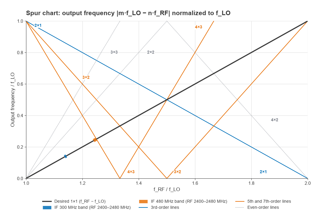
Figure 1 shows the two candidate plans for a 2400 to 2480 MHz receiver with a low-side LO. With a 300 MHz IF the band sits at x ≈ 1.14, clear of every line up to seventh order. With a 480 MHz IF the band sits at x ≈ 1.25, directly on the 4 × 3 line: at 2400 MHz input the LO is 1920 MHz, and 4 × 1920 − 3 × 2400 = 480 MHz, exactly the IF. A short script confirms that this 4 × 3 product stays within a 20 MHz IF bandwidth for channels from 2400 to 2410 MHz.
Spurious responses: the inverse problem
The spur chart answers which products land on the IF for a wanted signal. A receiver also has to reject unwanted inputs at other frequencies that convert to the IF. For a given LO, any input satisfying |m·fLO − n·fin| = fIF is a spurious response:
fin = (m·fLO ± fIF) / n
The most important are:
- Image (1 × 1): fLO − fIF for a low-side LO, 2·fIF below the wanted signal. It converts with full mixer efficiency, so only filtering or an image-reject mixer stops it. See image frequency and image rejection.
- Half-IF (2 × 2): fRF − fIF/2 for a low-side LO. It sits only half an IF away from the wanted signal and is suppressed only by mixer balance and whatever the preselector provides.
- IF feedthrough (0 × 1): an input at the IF itself leaking straight through the mixer.
- LO harmonic responses (m × 1): inputs near m·fLO ± fIF, often well outside the band but still a concern for wideband front ends.
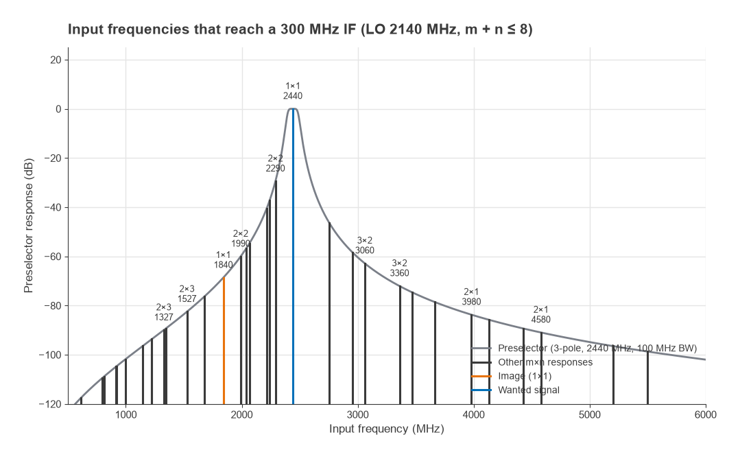
Figure 2 plots every response up to m + n = 8 for the 2440 MHz channel against a 3-pole Butterworth preselector centred at 2440 MHz with 100 MHz bandwidth. The image at 1840 MHz sees 68.7 dB of filter rejection in this model, the half-IF response at 2290 MHz only 29.5 dB, and the 2 × 1 response at 3980 MHz 83.7 dB. The half-IF response is usually the hardest to reject because it sits so close to the band. These figures come from an ideal filter model; real filters reach a stopband floor set by layout and parasitic coupling, and data-sheet rejection should be used in a real plan.
IF selection trade-offs
Raising the IF pushes the image and half-IF responses further from the band, where the preselector removes them more easily. Lowering the IF makes the IF filter, IF amplifier and ADC easier and cheaper, and improves IF filter selectivity for a given resonator Q, because the channel bandwidth becomes a larger fraction of the IF. The main considerations are:
- Image and half-IF rejection: set by preselector selectivity at fRF − 2fIF and fRF − fIF/2 (low-side LO).
- In-band spur crossings: the IF must not place the band on a low-order spur line.
- IF filter feasibility: a narrow channel filter at a high IF needs very high Q; standard SAW, crystal or ceramic filter frequencies often decide the IF in practice.
- Sampling: the IF and its bandwidth must suit the ADC sample rate, including any deliberate undersampling.
- LO placement: high-side or low-side injection changes the image location and whether the LO falls inside a neighbouring band. LO harmonics and the synthesizer reference must also stay out of the band; see PLL frequency synthesis.
- Coexistence: the LO, IF and their harmonics must not land on other radios in the same product, a topic covered in RF coexistence.
Worked example: choosing an IF for 2400 to 2480 MHz
Assume a single-conversion receiver with a low-side LO, a 20 MHz channel, and the 3-pole, 100 MHz preselector used above. The rejection figures are worst case across the band, computed from the Butterworth response |H|2 = 1/(1 + W6) with W = (f/f0 − f0/f)·f0/BW. Spur crossings were checked for every channel up to m + n = 9.
| IF (MHz) | Image band (MHz) | Image rejection | Half-IF band (MHz) | Half-IF rejection | In-band spur crossing |
|---|---|---|---|---|---|
| 70 | 2260–2340 | 18.7 dB | 2365–2445 | 0 dB | None |
| 140 | 2120–2200 | 42.3 dB | 2330–2410 | 0.2 dB | None |
| 300 | 1800–1880 | 66.6 dB | 2250–2330 | 21.2 dB | None |
| 480 | 1440–1520 | 82.8 dB | 2160–2240 | 37.3 dB | 4 × 3, channels 2400–2410 MHz |
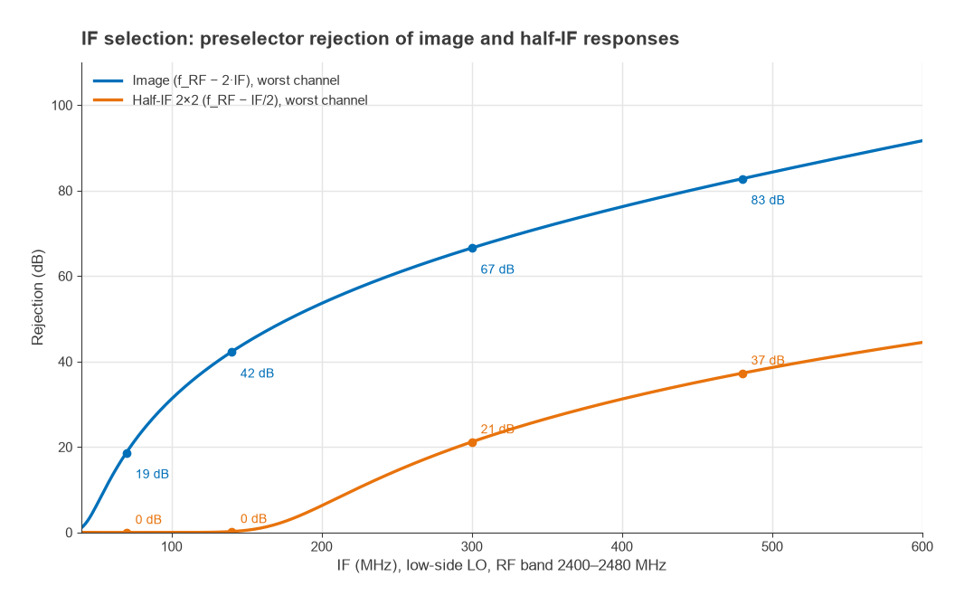
A 70 MHz IF fails on image rejection, and its half-IF response falls inside the band itself, so a strong in-band signal 35 MHz below the wanted channel converts through the 2 × 2 product with no filter help at all. A 140 MHz IF fixes most of the image problem but still has its half-IF response in the band. A 480 MHz IF gives the best rejection but puts the lower channels on a seventh-order spur. A 300 MHz IF is the best balance in this example: 66.6 dB of image rejection from the preselector alone, the half-IF response outside the band with 21.2 dB of filter rejection added to the mixer’s own 2 × 2 suppression, and no crossings up to ninth order. Figure 3 shows how both rejections grow with IF.
If a low IF is needed for other reasons, the alternative is to cancel the image rather than filter it, using a quadrature mixer. That route leads to the low-IF and zero-IF architectures, which use the IQ demodulator described elsewhere in this section.
How to build a frequency plan
- Write down the RF band, channel bandwidth and any neighbouring bands or radios that must be protected.
- List candidate IFs, usually starting from standard filter frequencies and ADC-friendly values, and both high-side and low-side LO options.
- For each candidate, compute every m × n product up to at least seventh order across all channels and reject plans with in-band crossings.
- Compute the image, half-IF and other spurious-response frequencies and the preselector rejection at each, adding the mixer’s spur suppression from its data sheet.
- Check LO and reference harmonics and IF harmonics against the RF band and against other radios.
- Choose the plan with adequate margin on every response, then set mixer drive levels and confirm spur levels by measurement.
The same method applies to transmit upconverters and, one conversion at a time, to multi-stage converters. The mixer topologies that set spur levels are compared in mixer types, and the receiver context is covered in Radio Architectures Part 2: Receivers, LOs and Mixers.
Frequently asked questions
How do you choose an IF frequency?
Pick the IF high enough that the preselector rejects the image and half-IF responses by the required amount, and check that no low-order m × n spur crosses the band. Then confirm that the IF suits available filters and the ADC. The final choice is the lowest IF that meets all spur and rejection requirements with margin.
What is a mixer spur chart?
A spur chart plots the output frequency of every m × n mixing product on normalized axes. The operating band appears as a segment on the wanted 1 × 1 line, and any other line crossing that segment marks a spur that lands on the IF. It shows at a glance which frequency ratios to avoid.
What is the half-IF spur?
It is the 2 × 2 response at half an IF from the wanted signal, on the same side as the LO. Twice its frequency minus twice the LO equals the IF. Because it is so close to the band it is hard to filter, and it relies on mixer balance and a sufficiently high IF.
Related topics
Preselector and IF filter requirements are defined in RF filter specifications. Intermodulation between two input signals, which is a different mechanism from mixer spurs, is covered in intermodulation and intercept points. Terms used on this page are defined in the wireless terms glossary.