

Cascaded IP3 is the third-order intercept point of a complete chain of stages, calculated from each stage’s own intercept and the gain in front of it. For input-referred values it follows 1/IIP3tot = 1/IIP31 + G1/IIP32 + G1G2/IIP33 + …, with every term in linear units. Gain ahead of a stage makes that stage’s distortion count for more, so later stages usually set the linearity of a receiver.
That is the mirror image of noise, where the first stage dominates. The tension between the two, and how to split gain along a lineup to satisfy both, is the practical problem this page works through. It belongs to the linearity and distortion section and assumes the single-stage definitions of IIP3 and OIP3 from Radio Architectures Part 3.
The cascaded IP3 formula
Consider a chain of N stages with available power gains G1, G2, … and input-referred intercepts IIP31, IIP32, …. Each stage produces third-order intermodulation that, referred back to the chain input, is divided by the cube of the gain ahead of it while the wanted signal is divided only by that gain. Working through the algebra for the worst case, where all IM3 voltages add in phase, gives
1/IIP3tot = 1/IIP31 + G1/IIP32 + G1G2/IIP33 + … + G1G2…GN−1/IIP3N
The equivalent output-referred form divides each stage’s OIP3 by the gain that follows it:
1/OIP3tot = 1/(OIP31G2G3…GN) + 1/(OIP32G3…GN) + … + 1/OIP3N
The two forms agree, with OIP3tot = IIP3tot × Gtot. All intercepts must be in watts or milliwatts and all gains as power ratios. Adding dB values directly is the most common mistake made with this formula.
Coherent and power addition
The formula above assumes the IM3 products of every stage arrive in phase, so their voltages add. That is the conservative case and the one normally used for budgeting. If the stages’ IM3 products have unrelated phases, their powers add instead, giving 1/IIP3tot2 = Σ(Gbefore,i/IIP3i)2. The power-addition result is always better, typically by one to two dB for a chain where two stages contribute similar amounts. Measured cascades usually fall between the two, because reactive matching networks and mixer phase shifts rotate the products by amounts that are hard to predict.
Passive stages and mixers
A passive filter or attenuator is treated as a stage with a very high IIP3, so its own term is negligible, but its loss still counts in the G products that scale every later term. A loss in front of the chain therefore improves IIP3 dB for dB, exactly as it worsens noise figure. A mixer is entered with its conversion gain (often negative for a passive mixer) and its IIP3 as measured with the intended LO drive.
How to calculate cascaded IIP3, step by step
- List every stage in signal order with its gain (dB), noise figure (dB) and IIP3 (dBm). Convert OIP3 to IIP3 where needed: IIP3 = OIP3 − G.
- Compute the cumulative gain ahead of each stage, in dB, by summing the gains of the stages before it.
- Convert each IIP3 to milliwatts and each cumulative gain to a linear ratio.
- For each stage, compute the term Gbefore/IIP3 in units of 1/mW.
- Sum the terms and invert. Convert the result back to dBm.
- Compare the terms. The largest one identifies the stage that limits the chain, and its share of the sum shows how much improving it can help.
- Run the Friis noise calculation on the same table so that both figures are judged together.
Worked example: a superheterodyne front end
The lineup is a preselect filter, an LNA, a mixer and an IF amplifier. The IF filter between mixer and IF amplifier is taken as lossless to keep the arithmetic short.
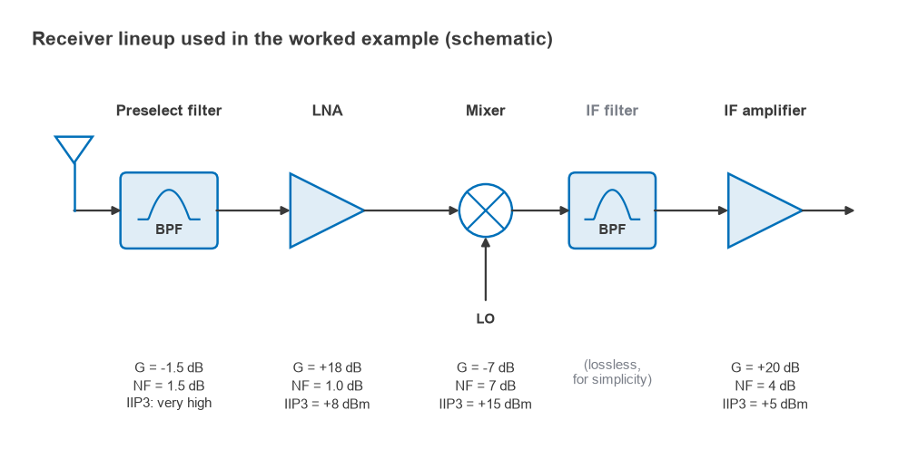
| Stage | Gain (dB) | NF (dB) | IIP3 (dBm) | Gain ahead (dB) | Gbefore/IIP3 (1/mW) |
|---|---|---|---|---|---|
| Preselect filter | −1.5 | 1.5 | very high | 0 | ≈ 0 |
| LNA | +18 | 1.0 | +8 | −1.5 | 0.7079 / 6.310 = 0.1122 |
| Mixer | −7 | 7.0 | +15 | +16.5 | 44.67 / 31.62 = 1.413 |
| IF amplifier | +20 | 4.0 | +5 | +9.5 | 8.913 / 3.162 = 2.818 |
The sum of the terms is 0.1122 + 1.413 + 2.818 = 4.343 mW−1, so IIP3tot = 1/4.343 = 0.2303 mW, or −6.38 dBm. Total gain is −1.5 + 18 − 7 + 20 = 29.5 dB, giving OIP3tot = +23.1 dBm. As a check, the output-referred form uses OIP3 values of +26, +8 and +25 dBm for the LNA, mixer and IF amplifier, followed by 13, 20 and 0 dB of gain. That gives 1/7943 + 1/631 + 1/316 = 0.004873 mW−1, or +23.1 dBm, the same answer.
Three results stand out:
- The IF amplifier supplies 65 percent of the total, the mixer 33 percent and the LNA under 3 percent. The LNA’s own +8 dBm IIP3 hardly matters, because only 1.5 dB of loss sits ahead of it.
- Referred to the chain input, the IF amplifier alone would limit the system to −4.5 dBm and the mixer alone to −1.5 dBm. The cascade is worse than either because their contributions add.
- If the IM3 products added in power rather than voltage, the result would be −5.0 dBm, about 1.4 dB better. Budgeting with −6.4 dBm leaves that difference as margin.
The same table gives a cascaded noise figure of 3.09 dB through the Friis formula (F = 1.413 + 0.366 + 0.090 + 0.170 = 2.038). Here the order reverses: the filter and LNA together contribute three quarters of the added noise, while the IF amplifier contributes about 16 percent. The cascaded noise figure page covers that calculation in detail.
What the result means for a two-tone test
With two interfering tones at −30 dBm each at the antenna, the input-referred IM3 level is 3Pin − 2IIP3 = −90 + 12.76 = −77.2 dBm, which is 47.2 dB below each tone. In a 1 MHz channel the receiver’s noise floor is −174 + 60 + 3.09 = −110.9 dBm. The IM3 product sits about 34 dB above that floor, so a pair of −30 dBm signals spaced correctly would block a weak wanted signal completely. The two-thirds rule gives the spurious-free dynamic range of this lineup as (2/3)(−6.38 + 110.9) = 69.7 dB in 1 MHz. The dynamic range and SFDR page derives that rule, and blocking and desensitization covers the related single-interferer problem.
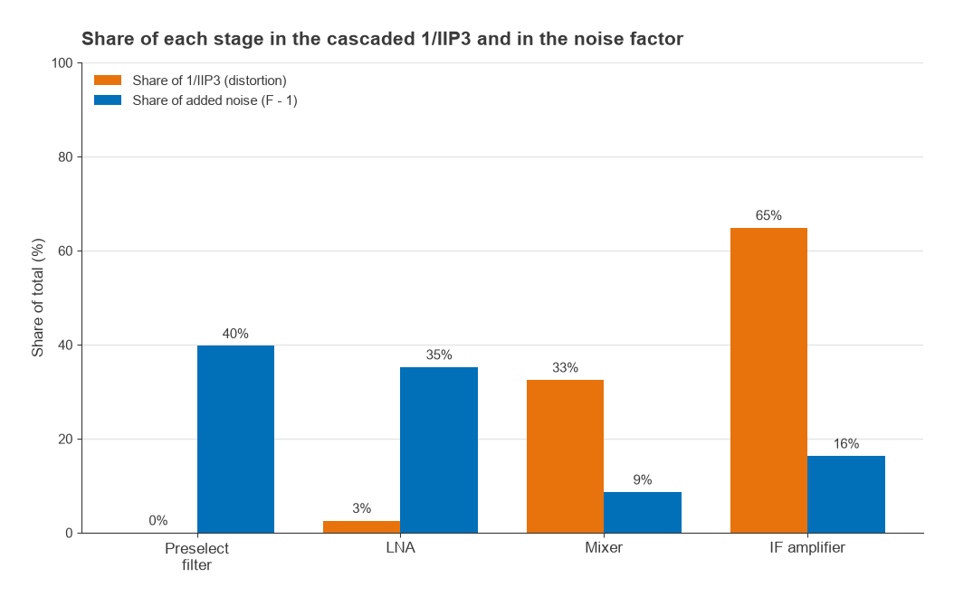
Gain distribution: the trade-off with noise figure
Gain placed early in a chain helps noise and hurts linearity. The Friis formula divides each later stage’s excess noise by the gain ahead of it, so more front-end gain suppresses the noise of the mixer and IF stages. The IP3 formula multiplies each later stage’s distortion term by the same gain, so more front-end gain drives those stages harder relative to their intercept.
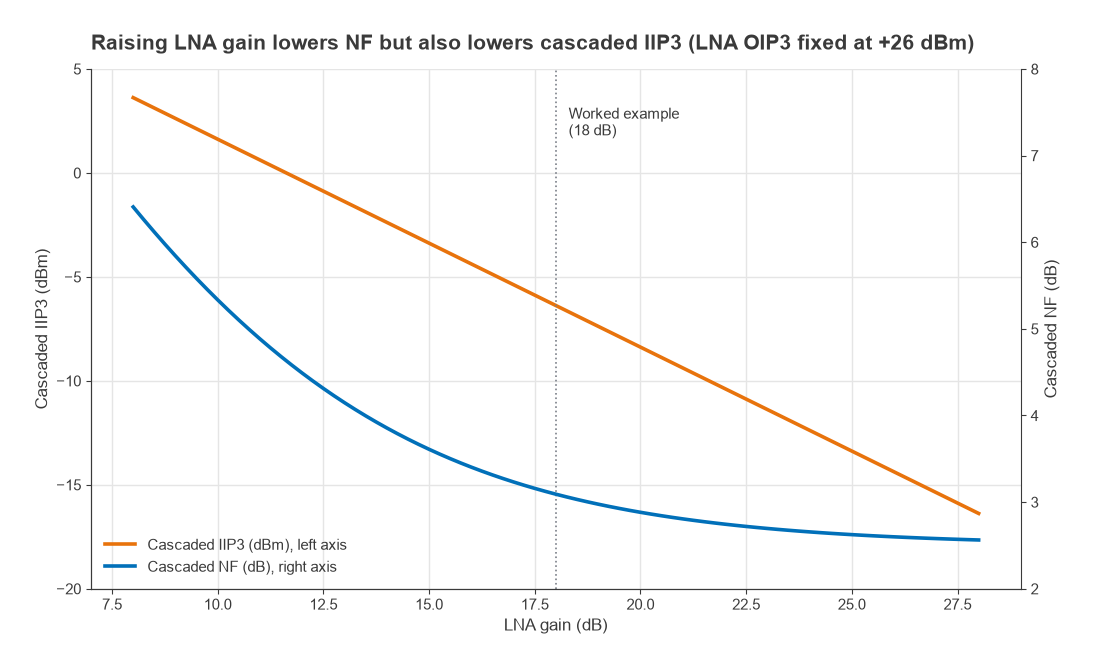
Holding the LNA’s OIP3 at +26 dBm and sweeping its gain shows the trade-off in numbers. Because the later stages dominate IP3, every extra dB of LNA gain costs almost exactly one dB of cascaded IIP3, while the noise figure improvement shrinks quickly.
| LNA gain (dB) | Cascaded NF (dB) | Cascaded IIP3 (dBm) |
|---|---|---|
| 10 | 5.33 | +1.6 |
| 14 | 3.86 | −2.4 |
| 18 | 3.09 | −6.4 |
| 22 | 2.75 | −10.4 |
| 26 | 2.60 | −14.4 |
Going from 18 to 26 dB of LNA gain buys 0.5 dB of noise figure and costs 8 dB of IIP3. Going from 18 down to 10 dB buys 8 dB of IIP3 and costs 2.2 dB of noise figure. Somewhere in between is the gain that maximises dynamic range for the application, and it is usually lower than the gain that minimises noise figure alone. The sensitivity requirement fixes the maximum NF, the expected interferer levels fix the minimum IIP3, and the LNA gain is chosen to meet both with similar margin.
Fixing the limiting stage
In the example the IF amplifier is the obvious target. Two changes are possible without touching the front end:
- Keep its gain at 20 dB but use a part with IIP3 of +15 dBm (OIP3 +35 dBm). Cascaded IIP3 improves from −6.4 to −2.6 dBm, with no change to noise figure.
- Keep its OIP3 at +25 dBm but cut its gain to 12 dB. Cascaded IIP3 becomes −2.9 dBm and noise figure stays at 3.09 dB, but total gain drops to 21.5 dB, which the ADC or demodulator that follows may not accept.
The general rule is that a stage’s OIP3 should rise with its position in the chain, since each later stage handles a larger signal. Filtering between stages helps too. An IF filter that removes out-of-channel interferers before the IF amplifier means that amplifier never sees the two-tone pair at all. The cascade formula, which assumes both tones pass every stage, then overstates the distortion. Real lineups are often analysed twice: once with in-band tones, where the formula applies directly, and once with out-of-band interferers attenuated by each filter in turn.
Limits of the cascade calculation
- It assumes each stage is weakly nonlinear and operated well below compression. Near P1dB the IM3 slope departs from 3:1 and intercept-based predictions fail.
- It uses gains and intercepts measured in 50 Ω. Mismatch between stages changes both the gain and the voltage swing each stage sees.
- Datasheet IIP3 values are usually typical figures at room temperature for a specific tone spacing and bias. Worst-case values over temperature can be several dB lower.
- It ignores second-order products, which matter in zero-IF and wideband receivers, and reciprocal mixing from LO phase noise.
A spreadsheet or short script that holds the lineup table, the Friis sum and the IP3 sum side by side is the standard tool for this work. Radio Architectures Part 15 builds that table for a complete radio.
Frequently asked questions
How do you calculate cascaded IIP3?
Convert every IIP3 to milliwatts and every gain to a linear ratio. Divide each stage’s IIP3 into the total gain ahead of it, add the results and invert the sum. The answer, converted back to dBm, is the IIP3 of the whole chain.
Why does the last stage dominate cascaded IP3?
Its distortion term is multiplied by all the gain in front of it. A stage with 30 dB of gain ahead of it contributes as if its IIP3 were 30 dB lower than the datasheet value, referred to the chain input.
Does a filter or attenuator change cascaded IIP3?
Its own distortion is normally negligible, but its loss reduces the gain ahead of every later stage. Loss at the front improves input-referred IIP3 by the same number of dB that it degrades noise figure.
Related topics
Cascaded IP3 closes out the linearity calculations collected in the linearity hub, which is part of the wider RF design guide. Mixer intercepts and spur behaviour are covered in Radio Architectures Part 2 and the mixers section.