


A transmission line termination is the load at the end of a line, and it determines how much of the incoming wave is absorbed and how much returns. A termination equal to the characteristic impedance absorbs the whole wave, while open, short and purely reactive terminations reflect all of it. Designers use both cases: matched loads to stop reflections, and deliberate mismatches to build stubs and transformers.
This article covers the standard terminations, the input impedance each one produces, and the practical limits of real loads. It follows the introduction to transmission line theory and forms part of the RF fundamentals section.
Matched termination
When ZL = Z0, the reflection coefficient is zero. There is no standing wave, the input impedance equals Z0 at every length, and all power not lost in the line reaches the load. Antenna ports, amplifier inputs and test equipment are designed to approach this condition over their operating band.
A matched dummy load, or 50 Ω termination, is also used on unused ports of couplers, splitters and circulators. An open port on these parts upsets their isolation, so these terminations matter even where no signal is wanted.
Standard load cases
The table gives the results from Γ = (ZL − Z0) / (ZL + Z0) for ideal loads. The reflection and transmission coefficients article derives these and treats complex loads.
| Termination | ZL | Γ | VSWR | Input impedance of length l |
|---|---|---|---|---|
| Matched | Z0 | 0 | 1 | Z0 |
| Short circuit | 0 | −1 | Infinite | +jZ0 tan βl |
| Open circuit | Infinite | +1 | Infinite | −jZ0 cot βl |
| Pure reactance | jX | Magnitude 1 | Infinite | Purely reactive |
| Other resistance | R | (R − Z0)/(R + Z0) | Finite | General Zin formula |
Short and open circuit terminations
A short circuit forces zero voltage at the end of the line, so the reflected wave cancels the incoming voltage there and the current doubles. An open circuit forces zero current, so the voltage doubles. Either way all the energy returns, and the line stores energy like a resonator.
Input impedance of stubs
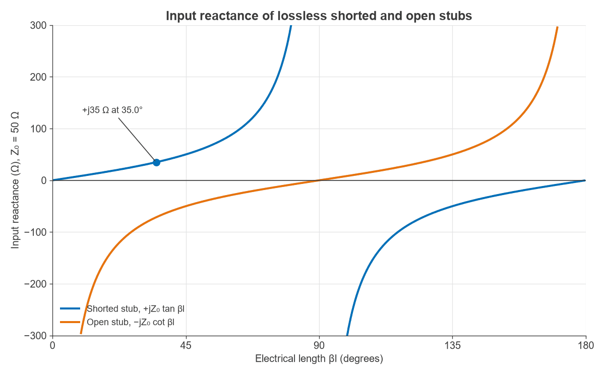
A lossless line ending in a short or open has a purely reactive input, as Figure 1 shows. The shorted stub looks inductive up to a quarter wavelength and capacitive from there to a half wavelength. The open stub does the opposite.
Stubs are therefore used in place of lumped inductors and capacitors, particularly above a few GHz, where discrete parts lose their ideal behaviour. A shorted quarter-wave stub looks like an open circuit at its design frequency. If the short is an RF bypass capacitor to ground, the stub can act as a DC feed or bias tee on an RF line.
Worked example: designing a stub
Suppose a 1.5 GHz matching network needs +j35 Ω from a 50 Ω coax line with velocity factor 0.70. The wavelength on the line is 0.70c / 1.5 GHz = 139.9 mm.
- Shorted stub: tan βl = 35/50, so βl = 35.0°, and l = 139.9 × 35.0/360 = 13.6 mm.
- Open stub for −j35 Ω: cot βl = 35/50, so βl = 55.0° and l = 21.4 mm.
An open end has fringing capacitance, which makes the stub appear electrically longer than its physical length. Practical stubs are usually trimmed against a measurement, and a Smith chart shows the whole design path in one view.
Resistive mismatch and the quarter-wave transformer
A resistive load other than Z0 gives a partial reflection. A line section can match such a load to a different system impedance. A quarter-wave line has an input of Zin = ZT2/ZL, so the matching section needs an impedance of:
ZT = √(Z0ZL)
For 100 Ω to 50 Ω, ZT = 70.7 Ω. With the same line type and frequency as the stub above, the section is 35.0 mm long. The match is exact only at the design frequency, and bandwidth grows if the section is split into several smaller impedance steps. Other approaches are covered by the impedance matching calculator, and the VSWR page shows what any leftover mismatch costs.
Real terminations and their parasitics
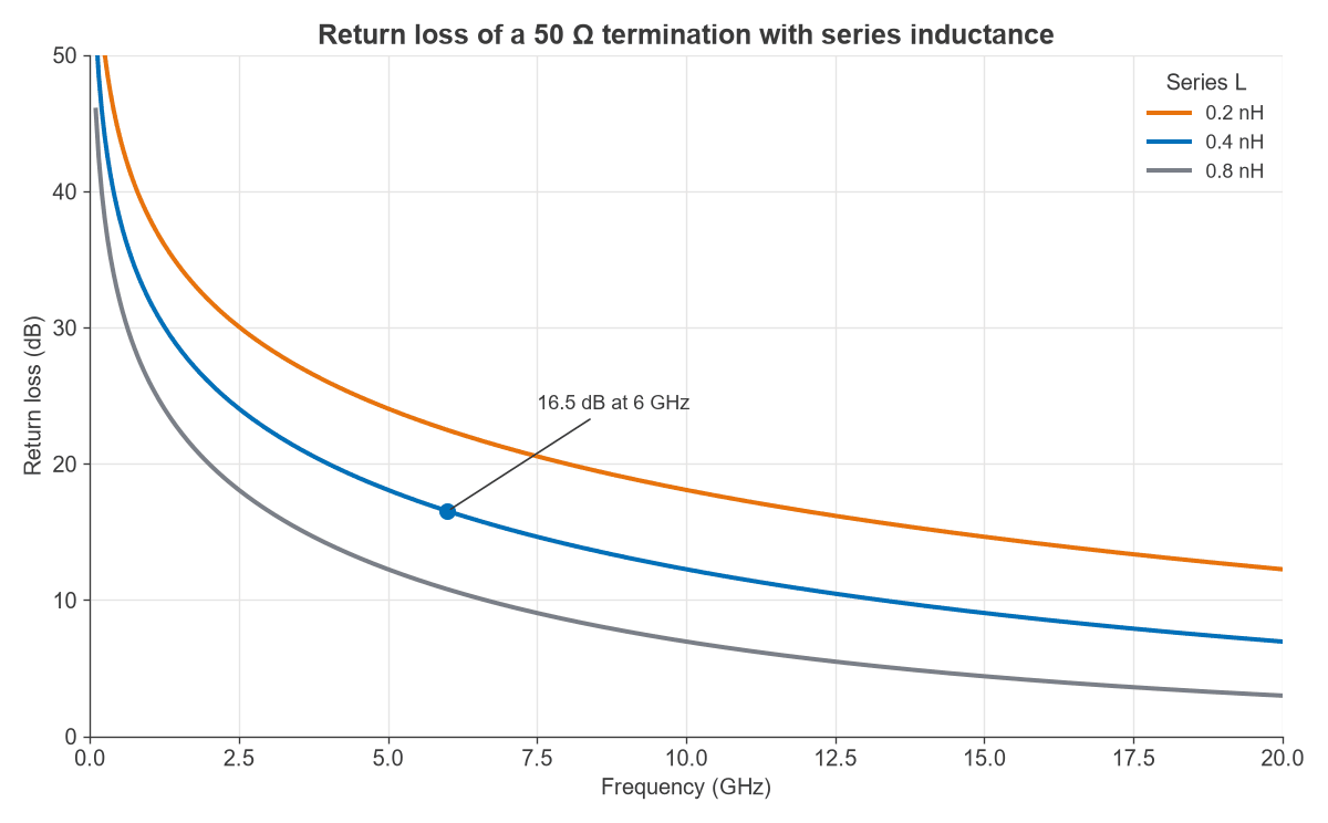
An ideal resistor exists only at low frequency. A chip resistor, its pad and its via to ground add series inductance and shunt capacitance. Figure 2 shows the result for a perfect 50 Ω resistor in series with 0.2, 0.4 and 0.8 nH.
Worked example: return loss of a chip termination
Take a 50 Ω load with 0.4 nH of series inductance, which is a plausible figure for a small resistor plus a ground via.
- At 6 GHz, X = 2π × 6 × 109 × 0.4 × 10−9 = 15.1 Ω.
- Then ZL = 50 + j15.1 Ω, and |Γ| = 0.149.
- The return loss is 16.5 dB.
The same load gives 32.0 dB at 1 GHz, 22.5 dB at 3 GHz and 10.8 dB at 12 GHz. By contrast, a resistance tolerance error is small in comparison. A 51 Ω resistor on a 50 Ω line gives Γ = 0.0099, a return loss of 40.1 dB, so the inductance dominates long before the resistor value does.
Parasitics also drive layout. Using several parallel ground vias, keeping pads small and using a thin substrate all lower the inductance. Precision coaxial terminations use tapered or distributed resistive elements to remain matched at much higher frequencies. A related point applies to measurements: if a fixture contributes parasitics, de-embedding can remove them from the data.
Why both ends of a line matter
A mismatch at the load alone sends one reflection back to a source that absorbs it, so the effect ends after one round trip. If the source is also mismatched, the wave reflects again and returns to the load, producing ripple in the frequency response with a period set by the line delay. The primary values in transmission line parameters fix that delay, and longer lines give finer ripple. Line loss weakens each pass, which is one reason a mismatch at the end of a lossy cable often does less damage than the same mismatch at the end of a short, low-loss one.
Choosing a termination in practice
- RF signal paths: match at both ends where possible, because any reflection at one end can return from the other.
- Unused ports: terminate couplers, circulators and hybrids in Z0 rather than leaving them open.
- Poorly matched loads: an attenuator between the source and load improves return loss by twice its value, at the expense of signal power.
- High-power loads: rate the termination for average and peak power, as discussed under line losses and power handling.
- High-speed digital lines: series resistors at the source and parallel or AC terminations at the load serve the same purpose for pulses.
Frequently asked questions
What happens if a transmission line is left unterminated?
An open end reflects the entire wave with Γ = +1, so a standing wave forms and the input impedance depends strongly on length and frequency. On a transmitter this can overstress the amplifier. A receive line loses signal and gains ripple, and an open circuit is only harmless on a line much shorter than a wavelength.
Why does a shorted stub not look like a short circuit?
The short is at the far end, and the wave has to travel down the line and back. The returning wave arrives with a phase shift of 2βl, so the input is reactive. A quarter wavelength shifts it by 180°, and the input looks open.
Is a termination always a resistor?
A matched termination is resistive at the design frequency, but it may be a network. Examples include an antenna, a series RC at the end of a digital line, and a high-power water or air-cooled load. Whatever the construction, it needs to absorb the wave and show Z0 across the band.
What return loss should a good termination have?
It depends on the application. General RF work often accepts around 20 dB, and precision calibration standards aim far higher. Return loss should always be quoted across the band in use, since parasitics make it fall with frequency.
Related topics
For how a wave behaves on the way to a load, see wave propagation in transmission lines. The choice of line itself is covered in characteristics and types of transmission lines.