

Receiver architecture selection is the choice of how a radio moves the wanted signal from RF to the digital domain, and it is set mainly by bandwidth, dynamic range, power and cost. Use a superheterodyne when selectivity and dynamic range matter most, zero-IF (direct conversion) when integration, power and cost dominate, and direct RF sampling when instantaneous bandwidth and flexibility justify the ADC power.
The three architectures were each covered in depth earlier in the Radio Architectures series: the superheterodyne in Part 2, Receivers, LOs and Mixers, direct conversion in Part 12, Zero-IF Receivers, and wideband digitising in Part 13, Direct RF Sampling and SDR. This page puts them side by side and gives a decision procedure, with numbers that show where each one runs out of room.
The three architectures in one view
Figure 1 shows the signal paths. All three start with an antenna, a band filter and a low-noise amplifier. They differ in where frequency translation happens and how much of it is done in analog hardware.
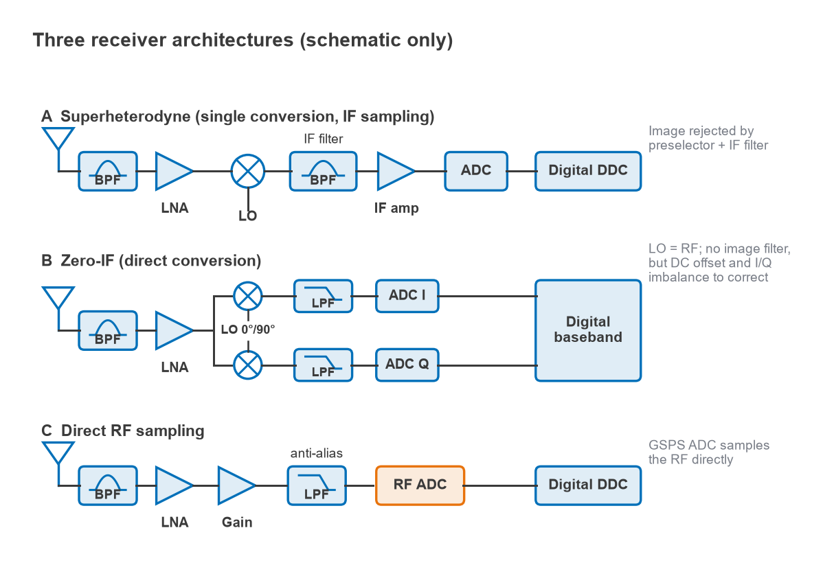
- Superheterodyne. One or more mixers translate the signal to a fixed intermediate frequency, where a sharp IF filter provides channel selectivity and an IF amplifier provides most of the gain. Modern designs often sample the IF directly and finish the job in a digital downconverter.
- Zero-IF. A quadrature mixer driven by an LO at the carrier frequency translates the channel straight to baseband I and Q. Channel filtering is done with low-pass filters and in the digital domain. A close relative, low-IF, offsets the LO slightly to avoid DC.
- Direct RF sampling. A multi-gigasample ADC digitises a whole band, and frequency translation, filtering and decimation all happen in digital logic. The analog chain shrinks to filters and gain.
Decision matrix by bandwidth, dynamic range, power and cost
The matrix compares typical implementations. Real designs blur the lines, and the entries are relative judgements rather than fixed figures.
| Criterion | Superheterodyne | Zero-IF | Low-IF | Direct RF sampling |
|---|---|---|---|---|
| Instantaneous bandwidth | Limited by IF filter and ADC; narrow to moderate | Up to twice the baseband ADC bandwidth (I plus Q) | Narrow; the IF offset uses part of the ADC band | Widest; up to a full Nyquist zone |
| Selectivity and blocker tolerance | Best; analog IF filter removes blockers before the ADC | Moderate; blockers reach baseband and the ADC | Moderate; image is an adjacent channel | Lowest; every in-band signal reaches the ADC |
| Dynamic range | Highest, because gain is applied after filtering | Good, limited by DC offset, flicker noise and second-order distortion | Good, limited by image rejection | Set by ADC noise density and linearity |
| Power | Moderate; multiple LOs and IF stages | Low; one LO, simple baseband | Low | Highest; GSPS ADC and high-rate digital processing |
| Cost, size and integration | Highest part count; off-chip IF filters | Lowest; fully integrable on a single chip | Lowest; fully integrable | Few analog parts but an expensive converter and FPGA or ASIC |
| Frequency agility | Retune LO; IF fixed | Retune LO | Retune LO | Retune in software within the sampled band |
| Main impairments | Image, spurs from frequency plan, filter group delay | DC offset, LO leakage, I/Q imbalance, flicker noise, IM2 | Image from I/Q imbalance | Aliasing, ADC spurs, clock jitter, data rate |
Superheterodyne: selectivity first
The superheterodyne’s strength is that it can filter before it amplifies most of the signal. Strong adjacent signals are removed by the IF filter, so the later stages and the ADC only see the wanted channel and a little residue. That is why superhets remain the choice for spectrum analysers, high-performance communication receivers and many base stations.
The price is the image. A mixer with an LO at fLO converts both fLO + fIF and fLO − fIF to the same IF. For a 2440 MHz signal with a 140 MHz IF and a low-side LO at 2300 MHz, the image is at 2300 − 140 = 2160 MHz, 2fIF = 280 MHz away. The preselector ahead of the mixer has to attenuate 2160 MHz by whatever image rejection the system needs. A higher IF moves the image further out and eases the preselector, but makes the IF filter harder to build with a narrow bandwidth. That trade drives double-conversion designs and the frequency planning described in frequency planning and spurs and image frequency rejection.
Zero-IF: integration first
Direct conversion places the LO at the carrier, so the image is the signal’s own mirror around zero frequency. No image filter is needed and no IF filter either, which is why nearly every cellular handset transceiver and many Wi-Fi chips use zero-IF or a close variant. Channel selectivity moves into low-pass filters and digital filtering, which integrate easily.
The impairments move too. LO energy that leaks to the antenna port reflects back and self-mixes to DC. Second-order intermodulation in the mixer turns amplitude variation of a strong blocker into a baseband signal. Flicker noise in the baseband stages sits right on top of narrowband channels. And gain or phase mismatch between I and Q leaves a residual image that falls on the signal itself. Part 12 covers these in detail; the quadrature hardware behind them is explained in I/Q modulators and demodulators.
Worked example: image rejection from I/Q imbalance
For a gain ratio g between the I and Q paths and a phase error φ, the image rejection ratio is
IRR = 10 log[(1 + 2g cos φ + g2) / (1 − 2g cos φ + g2)]
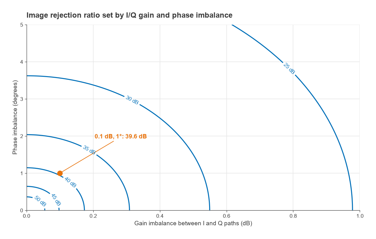
With a 0.1 dB gain imbalance (g = 1.0116) and a 1° phase error, IRR = 39.6 dB. In a zero-IF receiver the image lands on the wanted signal’s own spectrum, so it behaves like an error floor. An image 39.6 dB down corresponds to an error vector of about 10−39.6/20 = 1.0% of the signal. That is acceptable for QPSK and most 64-QAM links, but tight for 1024-QAM, which is why high-order systems add digital I/Q calibration. In a low-IF receiver the same 39.6 dB applies to an adjacent channel, which may be much stronger than the wanted one. Figure 2 maps IRR across gain and phase errors: staying above 40 dB needs gain matched within about 0.1 dB and phase within about 1°.
Direct RF sampling: bandwidth first
Direct sampling removes mixers and LOs from the receive path. One converter can capture several bands at once, and changing channel or standard becomes a software change. Converters running at several gigasamples per second make this practical through the lower microwave bands, as described in Part 5, ADCs and Receivers and Part 13.
The ADC is now the receiver, and its noise and full-scale level set sensitivity and dynamic range together. The data rate is also substantial: a 12-bit converter at 3 GSPS produces 36 Gb/s before decimation, and the digital downconverters that handle it account for much of the system power.
Worked example: how much gain does a direct-sampling front end need?
Take an illustrative 12-bit ADC sampling at 3 GSPS, with 60 dB SNR across its Nyquist band and a full-scale input of +1 dBm. Its noise spectral density is
NSD = −SNR − 10 log(fs/2) = −60 − 10 log(1.5 × 10⁹) = −151.8 dBFS/Hz
which is −150.8 dBm/Hz. Compared with the −174 dBm/Hz of thermal noise at 290 K, the ADC behaves like a stage with a noise figure of about 23.2 dB. To bring the cascade noise figure down, the front end needs gain. With a 1 dB noise figure LNA, the Friis formula gives a cascade NF of 5.3 dB with 20 dB of gain and 1.7 dB with 30 dB. But every decibel of gain lowers the signal level that drives the ADC to full scale: −19 dBm at the antenna with 20 dB of gain, −29 dBm with 30 dB.
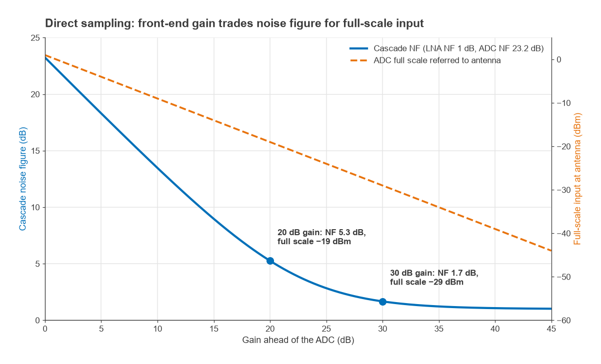
Figure 3 shows the trade. A superheterodyne avoids it by filtering away blockers before applying most of the gain; a direct-sampling receiver must accept every in-band signal at the ADC. The usable dynamic range is therefore roughly the ADC’s own, and the SFDR of the converter becomes a system specification. For wide-open receivers in crowded spectrum, that is often the deciding factor.
How to choose: a decision procedure
- Write down the instantaneous bandwidth, the strongest expected blocker relative to the weakest wanted signal, the power budget and the target cost.
- If the blocker-to-signal ratio exceeds what an ADC can handle after gain (compare it with the converter’s SFDR and the gain needed for noise figure), an analog IF filter is needed. Choose a superheterodyne.
- If the channel is narrow to moderate, cost and power are tight, and the standard tolerates the I/Q and DC impairments after calibration, choose zero-IF. Choose low-IF instead for very narrow channels where flicker noise and DC offset would sit in-band.
- If the system must capture hundreds of megahertz at once, cover several bands with one chain, or reconfigure in software, and power allows a GSPS converter, choose direct sampling.
- Check the result with a cascade analysis of noise figure, IP3 and the frequency plan, and verify it on the bench as described in Part 20, Measuring Radio Performance.
Hybrid designs are common. Many wideband receivers sample an IF of a few hundred megahertz (a superhet with direct sampling at the back), and mmWave radios often convert to an IF before a zero-IF or direct-sampling stage. Front-end modules handle the filtering and switching around whichever core is chosen.
Frequently asked questions
Which receiver architecture should I use?
Use a superheterodyne when strong blockers and high dynamic range dominate, zero-IF when integration, power and cost dominate, and direct sampling when instantaneous bandwidth and flexibility justify a high-speed ADC. Start from the blocker-to-signal ratio and the bandwidth, then confirm with a cascade analysis.
Is superheterodyne better than direct conversion?
Neither is better in general. The superheterodyne offers better selectivity and dynamic range; direct conversion offers lower cost, power and size. Most handsets use direct conversion, while most laboratory instruments use superheterodyne designs.
Why does a zero-IF receiver have no image problem?
Its image is the signal’s own mirror image around DC, not a separate frequency band. Quadrature mixing separates the two halves, and any I/Q imbalance appears as self-interference rather than as an external interferer.
When is direct RF sampling not a good choice?
When power is very limited or strong out-of-channel signals share the sampled band. All in-band signals reach the ADC, so blockers consume its dynamic range, and the converter and digital processing draw more power than a narrowband analog chain.
Related topics
The series starts with Radio Architectures Part 1, and the wider map is in RF design. Low-IF receivers have their own page under low-IF receivers, and terms are defined in the wireless terms glossary.