

Adjacent channel leakage ratio (ACLR) is a transmitter linearity metric: the ratio of the power integrated over the assigned channel to the power that leaks into a neighbouring channel, expressed in dB. The leakage comes mainly from spectral regrowth, where power amplifier nonlinearity spreads a modulated signal beyond its intended bandwidth. Adjacent channel power ratio (ACPR) describes the same quantity under a different name and, sometimes, slightly different measurement rules.
Every transmitter standard limits how much power may spill into adjacent channels, because that power is interference for other users. ACLR is often the specification that sets how far a power amplifier must be backed off, and therefore how efficient the transmitter can be. This page defines ACLR and ACPR, explains spectral regrowth, works through a simulated example, and covers measurement and the role of digital predistortion. It sits under the digital modulation topics in the RF design reference.
Definition of ACLR
ACLR compares two integrated powers, each measured over a defined bandwidth:
ACLR (dB) = 10log10(Pmain / Padj), where P = ∫ S(f) df over the relevant channel bandwidth
S(f) is the power spectral density. The main-channel and adjacent-channel bandwidths are set by the standard and need not be equal. ACLR is quoted separately for the upper and lower adjacent channels, and the worse of the two normally has to meet the limit. Many standards also specify an alternate-channel ratio, often written ACLR2, for the channel two spacings away. Because Padj is the smaller power, ACLR is a positive number and larger is better, although some datasheets quote the inverse ratio as a negative dBc value.
ACLR versus ACPR
The two terms are used interchangeably in most engineering conversation. ACLR is the term used in 3GPP specifications for UMTS, LTE and NR. ACPR is the older term, common in earlier cellular standards, in amplifier datasheets and in general linearity literature. Where differences exist they lie in the details: some ACPR definitions measure the adjacent power in a narrow bandwidth at a specific offset, or reference it to total carrier power rather than the power in a matched channel bandwidth. When comparing numbers from two sources, check the bandwidths, offsets and any filter weighting before assuming they mean the same thing.
Spectral regrowth: where the leakage comes from
A real transmitter leaks into adjacent channels for several reasons: phase noise of the LO, DAC and modulator noise, and imperfect filtering. In most high-power transmitters, though, the dominant cause is amplifier nonlinearity. Model the complex envelope through a power amplifier with a third-order term:
y(t) = u(t) − |u(t)|2u(t) / POIP3
Here u is the ideal output envelope with power in mW and POIP3 is the output third-order intercept in mW. The distortion term is a product of three copies of the signal, so its spectrum is the signal spectrum convolved with itself three times. A signal occupying bandwidth B produces third-order distortion spread across 3B, centred on the carrier. Fifth-order terms spread across 5B. The part of this distortion that falls inside the channel degrades EVM; the part that falls outside is spectral regrowth, the “shoulders” visible on any spectrum analyzer display of an overdriven transmitter. It is the modulated-signal counterpart of the two-tone intermodulation products.
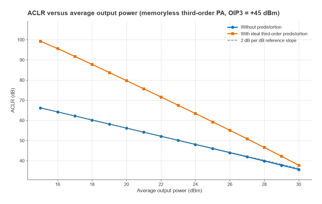
Because the distortion power grows as the cube of signal power while the wanted power grows linearly, the ratio between them changes by 2 dB for every 1 dB change in output power. In the third-order region, ACLR therefore degrades 2 dB per dB of increased output power, mirroring the 2:1 behaviour of two-tone IM3 relative to the carrier. AM-to-PM conversion, covered on the harmonic distortion and AM-PM page, adds further regrowth. Memory effects from bias networks and thermal time constants make the upper and lower sidebands unequal, which is why real measurements often show asymmetric ACLR.
Worked example: ACLR versus output power
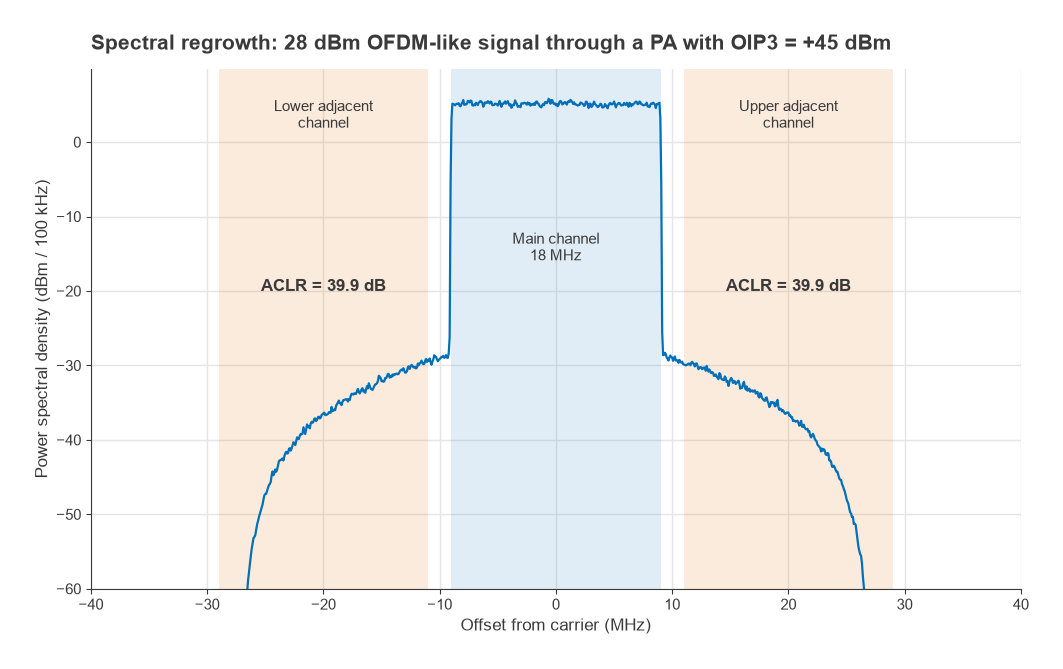
To see the numbers, a noise-like signal similar to OFDM was simulated: a band-limited complex Gaussian waveform occupying 18 MHz, with adjacent channels of the same bandwidth centred 20 MHz away (the layout of a 20 MHz LTE carrier, used only as an example). Its peak-to-average power ratio is about 9.8 dB at 0.01% probability, typical of OFDM. The signal was passed through the memoryless third-order model above with OIP3 = +45 dBm, and the channel powers were integrated from the computed spectrum.
| Average output (dBm) | Back-off from OIP3 (dB) | ACLR (dB) | ACLR with ideal third-order predistortion (dB) |
|---|---|---|---|
| 15 | 30 | 66.2 | 99.3 |
| 20 | 25 | 56.2 | 79.7 |
| 25 | 20 | 46.1 | 59.3 |
| 28 | 17 | 39.9 | 46.6 |
| 30 | 15 | 35.7 | 37.8 |
A least-squares fit to the lower half of the range gives a slope of −2.01 dB per dB, confirming the third-order rule (Figure 2). At 28 dBm the spectrum in Figure 1 shows shoulders about 34 dB below the in-band density, and the integrated ACLR is 39.9 dB on both sides. For comparison, a two-tone test at the same total power (25 dBm per tone) would give IM3 products 2 × (45 − 25) = 40 dB below each tone. The agreement here is close, but the relationship between two-tone IM3 and ACLR depends on the signal statistics and bandwidths, so it should be treated as a rough guide rather than a conversion rule.
If a specification demands 45 dB of ACLR, this amplifier must run at about 25.5 dBm average, roughly 19.5 dB below its OIP3. Every extra 3 dB of output power costs 6 dB of ACLR. That is the trade between linearity and efficiency that drives PA class selection and linearization.
ACLR, PA linearity and predistortion
An amplifier’s efficiency is highest near saturation, but signals with a high PAPR force it to operate well below that point to keep peaks out of compression. The required back-off is set by whichever limit is reached first, ACLR or EVM, and ACLR usually binds first because adjacent-channel limits are strict. The P1dB and OIP3 of the amplifier are the first indicators of how much back-off will be needed.
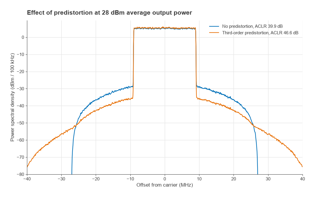
Digital predistortion (DPD) applies an inverse nonlinearity to the baseband signal so that the cascade of predistorter and amplifier is close to linear. In the example, the simplest inverse, upd = u + |u|2u/POIP3, cancels the third-order term but leaves a fifth-order residue. ACLR at 15 dBm improves from 66.2 to 99.3 dB, while at 28 dBm the improvement is only 6.7 dB (Figure 3) because the residue grows at 4 dB per dB and the signal peaks approach the limits of the model. Practical DPD uses higher-order polynomials with memory terms, adapted continuously from a feedback receiver, and can typically improve ACLR by 15 to 25 dB on a real amplifier, though results vary widely. No predistorter can push the output beyond saturation, so DPD is usually combined with crest factor reduction. The PA linearization page covers these techniques in depth.
Measuring ACLR
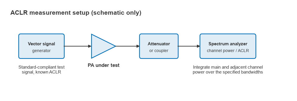
ACLR is measured with a spectrum analyzer using a channel-power method (Figure 4). The analyzer sweeps or captures the spectrum with a resolution bandwidth much narrower than the channel, uses an RMS detector, and integrates the power over the main and adjacent channel bandwidths. Some standards apply a filter weighting, such as a root-raised-cosine response, to each channel. Modern analyzers include preset ACLR measurements for common standards.
Three practical issues decide the accuracy:
- Source quality. The test signal has its own ACLR. If the source ACLR is 10 dB better than the device, uncorrelated leakage adds 10log10(1 + 0.1) = 0.41 dB of error, and correlated leakage could add up to 20log10(1 + 0.316) = 2.4 dB.
- Analyzer dynamic range. Too much power at the analyzer mixer generates distortion in the analyzer; too little lets its noise floor fill the adjacent channel. Set the input attenuation for the best balance, and use noise correction if available.
- Signal statistics. ACLR depends on the PAPR of the test waveform, so the waveform must match the standard’s test model. Measuring with a lower-PAPR signal flatters the amplifier.
The complete transmitter test procedure is discussed in Radio Architectures Part 20: measuring radio performance.
Typical requirements
Limits depend on the standard, the equipment class and the channel offset. As an approximate guide, cellular handset transmitters are commonly required to meet an adjacent-channel ACLR on the order of 30 dB, while base stations face limits closer to 45 dB, with alternate-channel limits stricter still. Designers usually target several dB of margin to cover production spread, temperature and antenna mismatch. Always take actual numbers from the current version of the applicable standard.
Frequently asked questions
What is ACLR?
ACLR is the ratio of the power in a transmitter’s assigned channel to the power leaking into an adjacent channel, each integrated over a defined bandwidth and expressed in dB. A higher value means less interference to neighbouring channels.
ACLR vs ACPR: what is the difference?
They describe the same effect. ACLR is the 3GPP term; ACPR is the older and more general term. Differences, where they exist, are in measurement details such as bandwidths, offsets and whether the reference is channel power or total carrier power.
Why does ACLR get worse by 2 dB for every 1 dB of output power?
Third-order distortion power grows as the cube of signal power, so it rises 3 dB for each 1 dB increase while the wanted signal rises 1 dB. The ratio therefore falls 2 dB per dB until fifth-order terms and saturation make it fall faster.
How does DPD improve ACLR?
DPD distorts the baseband signal in the opposite direction to the amplifier, so the cascade behaves more linearly and produces less regrowth. It allows the amplifier to run closer to saturation, at higher efficiency, while still meeting the ACLR limit.
Related topics
Amplifier-side background is in power amplifier classes, PA linearization and reading an RF amplifier datasheet. Signal-side background is in QAM, Radio Architectures Part 16: modulation, EVM and PAPR and transmitter architectures. Terms are defined in the wireless terms glossary.