
Software defined radio (SDR) is a radio in which filtering, tuning, demodulation and modulation are carried out by digital processing of sampled signals, so software rather than fixed circuits sets most of the receiver or transmitter’s behaviour. An analog RF front end still connects the antenna to an analog-to-digital converter (ADC) and a digital-to-analog converter (DAC), and that front end, together with the converters, sets the limits on sensitivity and strong-signal handling that no code can remove.
The practical question for an engineer is therefore where the analog work stops, what the converters can resolve, and how much of the digital load sits in an FPGA versus a host computer. This guide follows the signal from antenna to DSP, compares the three common front ends, and works through ADC dynamic range and sample rate with real numbers.
How software defined radio works: the signal chain from antenna to DSP
Figure 1 shows the full chain. On receive, the antenna signal is filtered, protected and amplified, translated in frequency if the architecture calls for it, and digitized. The sampled stream is far too fast for most general-purpose software, so a digital downconverter (DDC) in an FPGA or ASIC tunes to the band of interest, filters it and lowers the sample rate. The reduced stream crosses a link to a host, where DSP code demodulates and decodes it. Transmit runs the same path in reverse: the host produces baseband samples, a digital upconverter (DUC) raises the rate, the DAC creates an analog waveform, and the analog stages filter and amplify it.
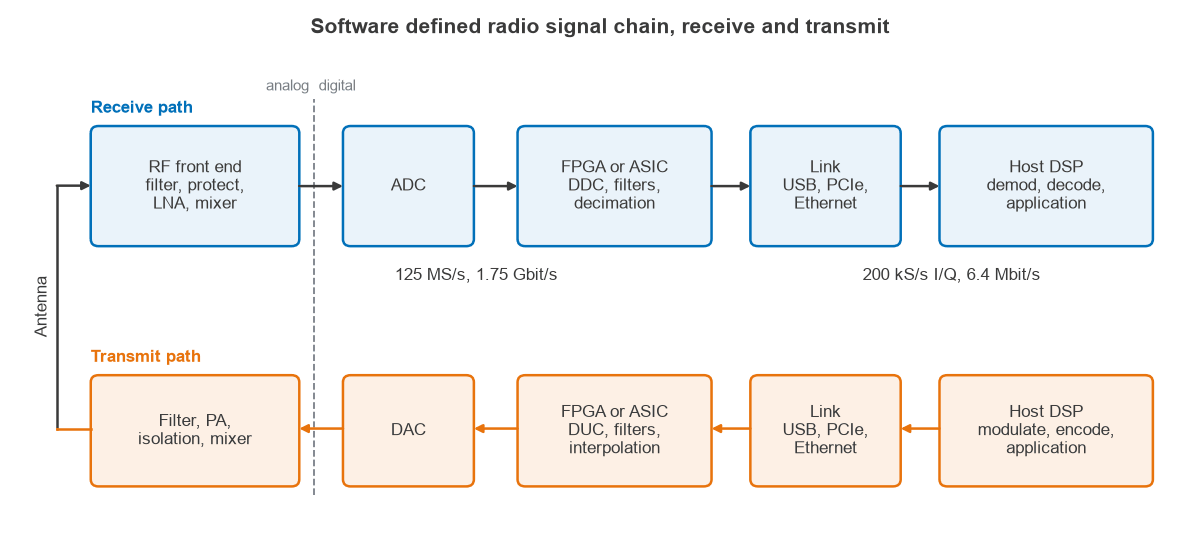
The rates annotated on the figure come from the worked example used later in this article. A 14-bit ADC at 125 MS/s produces 1.75 Gbit/s. After decimation to 200 kS/s of complex samples, with 16 bits each for I and Q, the host sees 6.4 Mbit/s. The sample-rate ratio is 625, and that reduction explains why a fast programmable device usually sits next to the converter.
Key SDR components and their roles
RF front end
The front end is everything between the antenna connector and the converter. It selects a band, sets the signal level at the ADC, and in many designs shifts frequency. Its noise figure and linearity carry directly into system performance, and it is the part most often underestimated when a radio is described as being defined by software. Duplexing or switching between receive and transmit also lives here in an SDR transceiver.
ADC and DAC
The ADC turns a continuous voltage into numbers. Its sample rate fixes the instantaneous bandwidth, its noise and distortion fix the usable dynamic range, and its aperture and clock quality limit performance at high input frequencies. The DAC does the inverse job on transmit. A DAC holding each sample for one clock period has a sinc-shaped response, with about 2.42 dB of droop at 0.4 fs, and it also produces images. The image of a tone at 0.4 fs falls at 0.6 fs, only 3.52 dB below the wanted tone, so an analog reconstruction filter is required. More detail on converter behaviour is on the ADCs page.
FPGA or ASIC
The FPGA, or a fixed ASIC in a volume design, handles the work that must keep pace with the converter clock. Typical blocks are a numerically controlled oscillator (NCO) and mixer, cascaded decimating filters, I/Q and DC correction, timestamping and packet framing. Deterministic timing is the main reason for placing logic here. A fast hopping waveform, or a response that must be returned within a fixed number of samples, cannot wait for an operating system to schedule a thread.
Host processor and data link
The host runs the parts of the radio that benefit from fast development: demodulators, decoders, protocol stacks, displays and logging. The link between the FPGA and the host is often the real bandwidth limit in a low-cost system. USB 2.0 signals at a nominal 480 Mbit/s and USB 3.0 at a nominal 5 Gbit/s, and usable payload is lower than both. A stream of 61.44 MS/s complex samples with 16 bits each for I and Q needs 1.97 Gbit/s, so sustained wideband capture also demands attention to host buffers and storage.
SDR software and programming
SDR programming usually means building a flowgraph of processing blocks or writing directly against a device driver. GNU Radio is a free and open-source toolkit that supplies signal processing blocks for building software radios, and it can run with external RF hardware or without hardware in a simulation-like environment. SoapySDR is an open-source, vendor-neutral C/C++ API and runtime library for SDR devices, with bindings for other languages including Python. A driver layer of this kind lets one application support several hardware platforms, though the application still has to account for each device’s sample rates, gain ranges and tuning behaviour.
SDR architecture: direct sampling versus superhet and zero-IF front ends
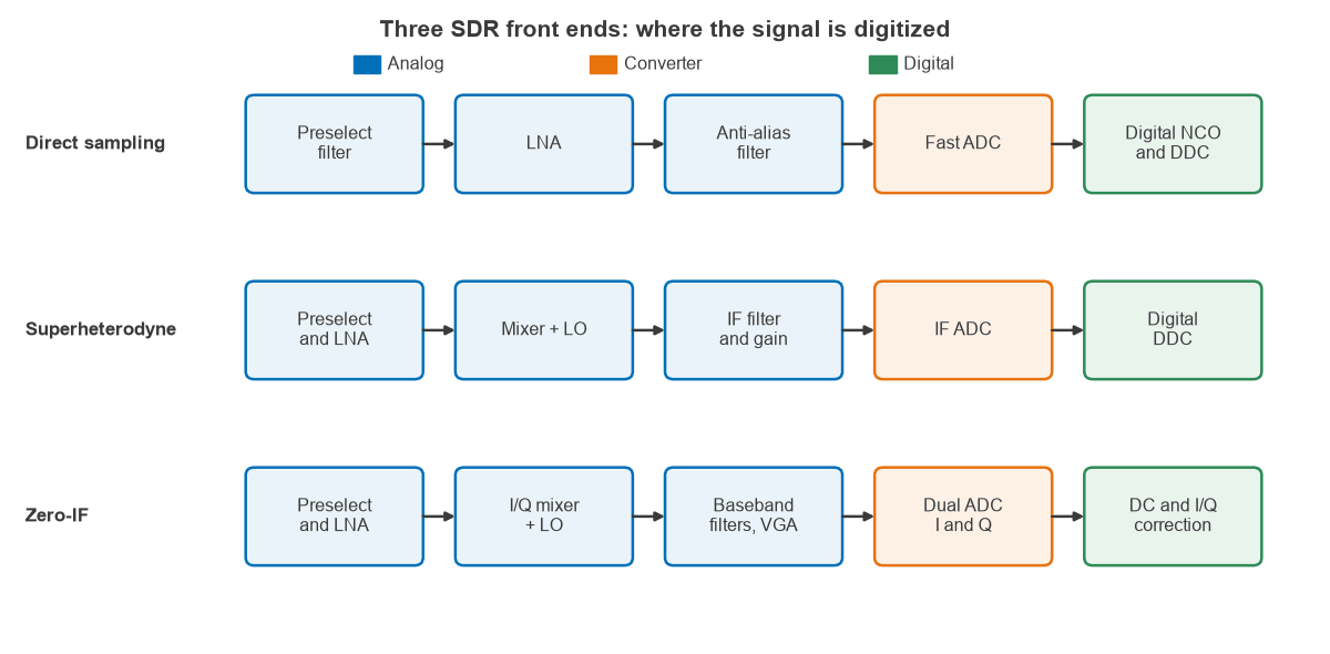
A software defined radio architecture is defined mostly by where the ADC sits relative to the mixer stages. Figure 2 compares the three main arrangements. The wider trade-offs between them are covered in the Radio Architectures series.
Direct RF sampling
Direct sampling places the ADC close to the antenna, with no analog mixer. Tuning is entirely digital, so several widely spaced channels can be extracted from one stream at the same time. The price is that the converter must handle every signal that reaches it, its clock jitter matters most, and the anti-alias filter becomes the main analog selectivity. Jitter-limited SNR for a full-scale input is -20 log10(2π f tj). With 0.5 ps RMS jitter that is 70.1 dB at 100 MHz and only 50.1 dB at 1 GHz, and at 1 GHz it takes 0.1 ps to reach 64.0 dB. Part 13 of the series covers this in depth: direct RF sampling and software defined radio.
Superheterodyne
A superhet translates the wanted band to a fixed intermediate frequency (IF), filters it there, and samples the IF with one ADC. The fixed IF filter gives strong analog selectivity before the converter, so the ADC sees fewer large signals. Spurious mixing products are a design cost, along with the image frequency, which must be removed by the preselector before the first mixer. Tuning range usually needs a tracking or switched filter bank, and the extra stages add size and power. Where blocker performance matters more than compactness, this remains a strong choice.
Zero-IF
A zero-IF, or direct-conversion, receiver mixes the band straight to DC using a quadrature LO, and samples I and Q with two ADCs. Complex sampling gives a bandwidth equal to the sample rate, the analog low-pass filters can be integrated, and one chip can cover a wide tuning range, which is why this design appears in many highly integrated SDR transceivers. Its weaknesses sit at DC: LO self-mixing creates offsets, flicker noise rises at low frequency, and even-order distortion lands in band. Gain and phase mismatch between I and Q also leaves a residual image. A mismatch of 0.1 dB and 1 degree limits image rejection to about 39.6 dB before digital correction. See zero-IF receivers for the mechanisms and fixes.
| Property | Direct sampling | Superheterodyne | Zero-IF |
|---|---|---|---|
| ADC input | RF | Fixed IF | Baseband I and Q |
| Analog mixing stages | None | One or more | One, quadrature |
| Main selectivity | Preselector and anti-alias filter | IF filter | Baseband filters |
| Typical weak point | Blockers, jitter, ADC power | Spurs, size, image response | DC offset, flicker noise, I/Q imbalance |
| Instantaneous bandwidth | Very wide | Set by IF filter | Wide, up to the complex sample rate |
| Multi-band capture | Natural | Needs parallel paths | Needs parallel paths |
ADC dynamic range and sample rate: worked examples
The numbers below use one assumed converter so that each result feeds the next. Take a 14-bit ADC sampling at fs = 125 MS/s, with a 1 V peak-to-peak full scale into 50 ohms and a measured SINAD of 72 dB. Distortion is assumed small enough that SNR and SINAD are equal. All values were computed in Python.
Ideal SNR and ENOB
An ideal N-bit converter driven by a full-scale sine has SNR = 6.02 N + 1.76 dB, which gives 86.04 dB for 14 bits. Effective number of bits (ENOB) reverses that formula using measured SINAD:
ENOB = (SINAD – 1.76) / 6.02 = (72 – 1.76) / 6.02 = 11.67 bits
This converter therefore behaves like a perfect 11.67-bit device. The other 2.33 bits of its output word mostly carry thermal noise, clock noise and distortion, which is why the bit count on a data sheet says little until SINAD is read alongside it.
Nyquist bandwidth
Real sampling at 125 MS/s supports a Nyquist bandwidth of fs/2 = 62.5 MHz. Complex I/Q sampling at the same rate supports 125 MHz, because the two streams separate positive and negative frequencies. In practice the anti-alias filter needs a transition band, so usable bandwidth is smaller, commonly taken as about 80 percent of the Nyquist figure.
Anything outside the chosen zone folds back. With fs = 125 MS/s, a signal at 100 MHz lies in the second Nyquist zone and appears at 25 MHz. So do signals at 150, 225 and 275 MHz, as well as a true 25 MHz input. Software cannot tell these apart after sampling, because the samples are identical. Spectral inversion in even zones can be undone digitally, but aliases cannot.
Noise floor
Full scale of 1 V peak-to-peak is 0.354 V RMS, or +3.98 dBm in 50 ohms. With 72 dB SNR, total noise is -68.02 dBm spread across 62.5 MHz (77.96 dB-Hz), so noise spectral density is:
NSD = -68.02 – 77.96 = -145.98 dBm/Hz
Thermal noise at 290 K is -173.98 dBm/Hz. The difference is the ADC’s equivalent noise figure of 28.0 dB, a reminder that a raw ADC is a poor receiver input without gain ahead of it.
Processing gain
Filtering to a narrow channel removes most of that noise. For a 25 kHz channel:
Processing gain = 10 log10(62.5 MHz / 25 kHz) = 33.98 dB
Noise in the channel is -145.98 + 43.98 = -102.0 dBm, and the dynamic range from full scale down to that noise is 72 + 33.98 = 105.98 dB, about 106 dB. Every halving of channel bandwidth adds about 3 dB, as Figure 3 shows.
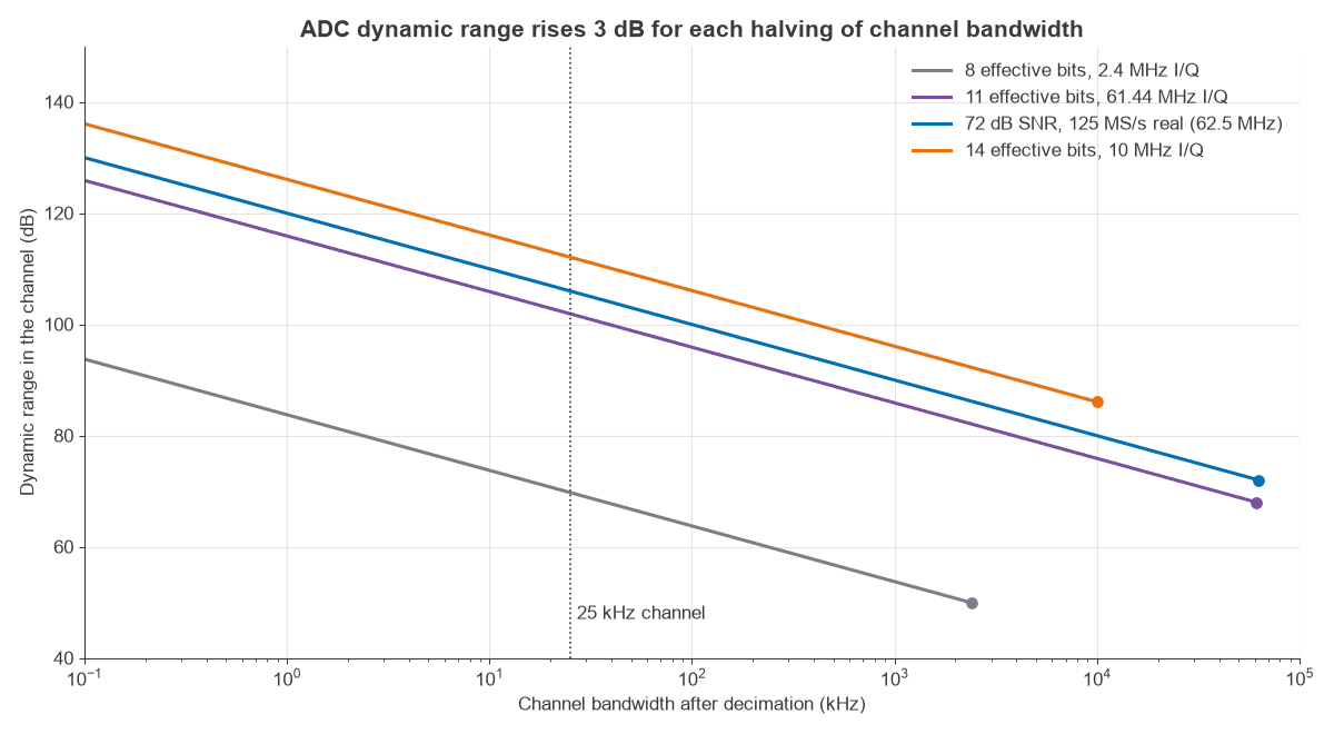
Processing gain has limits. It applies to noise that is spread evenly across the band. A narrowband spur from ADC nonlinearity stays at the same level however narrow the filter becomes, so spurious-free dynamic range (SFDR) can set the working limit before the noise floor does. The gain also does nothing for clipping: a signal above full scale overloads the converter however narrow the channel.
Table 1 applies the same formula to four cases, each treated as ideal at its stated effective resolution, with a 25 kHz channel. Narrow channels can favour a slower converter with more effective bits, as the last row shows.
| Case | SNR (dB) | Nyquist bandwidth | Processing gain (dB) | Dynamic range in 25 kHz (dB) |
|---|---|---|---|---|
| 8 effective bits, 2.4 MHz I/Q | 49.9 | 2.4 MHz | 19.8 | 69.7 |
| 11 effective bits, 61.44 MHz I/Q | 68.0 | 61.44 MHz | 33.9 | 101.9 |
| 72 dB SNR, 125 MS/s real | 72.0 | 62.5 MHz | 34.0 | 106.0 |
| 14 effective bits, 10 MHz I/Q | 86.0 | 10 MHz | 26.0 | 112.1 |
Adding an LNA
Gain ahead of the ADC lowers the noise floor at the antenna but also lowers the signal level that reaches full scale. The Friis equation gives the system noise figure, Fsys = FLNA + (FADC – 1) / GLNA, with FADC = 630 for 28 dB. Table 2 uses an LNA with a 3 dB noise figure and the same 25 kHz channel.
| LNA gain | System NF | Full scale at input | Noise floor in 25 kHz | Dynamic range |
|---|---|---|---|---|
| None | 28.0 dB | +4.0 dBm | -102.0 dBm | 106.0 dB |
| 20 dB | 9.2 dB | -16.0 dBm | -120.8 dBm | 104.8 dB |
| 30 dB | 4.2 dB | -26.0 dBm | -125.8 dBm | 99.8 dB |
The floor improves by about 19 dB with 20 dB of gain, at a cost of only 1.2 dB of dynamic range. The next 10 dB of gain buys another 5 dB of sensitivity and gives up 5 dB of dynamic range, and further gain would give steadily less. A sensible gain setting brings the external noise, or the system noise, a few dB above the ADC floor and stops. The article on LNAs for SDR applies this to real receive setups, and RF amplifiers covers the device side.
What the front end must still do
Software can remove a signal that the converter captured cleanly. It cannot repair one that was clipped, aliased or buried. The analog stages have to handle these jobs:
- Reject aliases. In the example above, a -20 dBm signal at 150 MHz lands on the 100 MHz channel at 25 MHz. Reaching the -102 dBm channel floor takes 82 dB of rejection, which is why anti-alias filter order drives so much of a wideband design.
- Keep strong signals out of the converter. A nearby broadcast or cellular transmitter can consume the whole ADC range. Preselection removes it before it adds to the composite peak level. Multiple carriers add to a higher crest factor than a single sine, so average level must sit below full scale.
- Set the noise figure. The first active stage dominates the cascade, so loss before it, such as filters and cable, adds directly to system noise figure.
- Stay linear. An LNA or mixer that compresses or creates intermodulation products puts false signals in band. No digital filter can separate these from real signals on the same frequency. The RF noise hub covers noise and distortion budgets.
- Control gain. Automatic gain control keeps the signal in the converter’s range, and its steps and settling time should suit the waveform.
- Provide a clean LO and clock. Phase noise on the LO or sample clock transfers onto every signal. A strong adjacent signal can then spread noise over a weak one through reciprocal mixing.
- Protect the input. Limiters and ESD protection guard the first stage, and any transmit path needs isolation from it.
- Clean up transmit. DAC images, harmonics and PA distortion must be filtered to meet the emission limits for the band. The raw output of a wideband transmitter is rarely suitable for connecting to an antenna without a band filter.
SDR frequency range and bandwidth
These two figures are often confused. Frequency range is how far the radio can tune, and in a mixer-based design it depends on the LO and front end rather than the ADC. Instantaneous bandwidth is the slice of spectrum captured at once, and it is set by sample rate and filters. A radio may tune across many gigahertz yet see only a few megahertz at a time. Sweeping a narrow window across a wider span can build a slow picture of a band, but short transient signals between visits will be missed.
How to choose SDR hardware
There is no single best platform, so selection should start from the signal and the environment rather than a list of features. These criteria cover most decisions:
| Criterion | What to check |
|---|---|
| Frequency range | Tuning coverage, plus filter and antenna coverage at the band of use |
| Instantaneous bandwidth | Widest signal or group of signals that must be captured at once |
| ADC resolution and SNR | Measured SNR, SINAD and SFDR at the operating frequency, not only bit count |
| Noise figure | System figure at the gain setting that will really be used |
| Front-end filtering | Built-in preselection, switched bands, and space for external filters |
| Transmit capability | Output power, DAC images, duplex mode and any path isolation |
| Channels and synchronization | Number of coherent channels, shared clock and LO, and timestamping for MIMO or direction finding |
| Clock quality | Reference stability, phase noise and external reference input |
| FPGA resources | Room for custom logic, and whether the toolchain is open to users |
| Host link | Sustained data rate, and latency for real-time response |
| Software support | Driver maturity, supported languages and frameworks, documentation |
| Environment | Power, size, temperature range and shielding for the place of use |
Work through the budget before choosing. Estimate the strongest signal likely to arrive at the input, the weakest one that must be recovered, and the channel bandwidth. The difference between strongest and weakest, compared with the Table 1 figures after a margin for crest factor, shows whether the converter alone is enough or the design needs analog filtering. Published SNR and SFDR should be read at the frequency and sample rate of interest, since both change across the operating range.
Typical uses of software defined radio
Software defined radio suits applications where signals change, where several must be handled at once, or where a design has to evolve after hardware is fixed. Common uses include:
- Radio system prototyping and research, where a new waveform can be tested over the air without building custom silicon.
- Spectrum monitoring and interference hunting across a wide band.
- Cellular and other base station equipment, where digital filtering and upgradeable baseband processing support multiple carriers and standards.
- Test and measurement, including signal generation, signal analysis and channel sounding.
- Amateur radio transceivers and receivers, with panoramic spectrum displays and software-based modes.
- Reception of signals such as ADS-B aircraft broadcasts at 1090 MHz and GNSS, along with weather satellite and other digital downlinks.
- Multi-waveform defence and public-safety radios that must interoperate with several systems.
- Teaching of DSP and communications, since real signals can be inspected at each stage.
More examples of where these techniques sit in a finished product appear in RF design applications. Before transmitting with any SDR, check the local licensing rules and emission limits for the band.
Frequently asked questions
What does SDR stand for in radio and telecom?
In radio and telecom, SDR stands for software defined radio, sometimes written software-defined radio. It describes a radio whose physical-layer processing is done mainly in software or programmable logic. The same letters have other meanings in unrelated fields.
What is SDR in ham radio?
In amateur radio, an SDR is a receiver or transceiver that digitizes a section of a band and shows it as a live spectrum and waterfall display. An operator can see activity across the band at once and tune by clicking on a signal. The same radio can gain new modes through software updates, while the analog filtering and transmit stages still decide much of its performance on crowded bands.
Does a software defined radio need a computer?
Not always. Many SDRs stream samples to a PC, but others run the DSP in an internal processor and present ordinary radio controls. Embedded designs run entirely on an FPGA and small processor. The term describes how signals are processed, not the type of user interface.
What is the difference between an SDR receiver and an SDR transceiver?
An SDR receiver only has the ADC path, so it can monitor signals but cannot emit them. An SDR transceiver adds a DAC, transmit filtering and usually a low-power output stage, and it needs isolation between paths. Full-duplex operation also depends on the radio’s isolation and any external duplexer.
Related topics
For the wider design context, start at the RF design hub, then read about direct RF sampling and zero-IF receivers in the Radio Architectures series, and the ADCs page. RF calculators can help with cascade and noise budgets.