


Spatial multiplexing in 5G networks means sending up to eight independent MIMO layers to one device on the NR downlink, all on the same time and frequency resources. The base station learns the channel through CSI-RS reports or uplink sounding, precodes each layer, and adds a DM-RS for each layer so the device can separate them. With four layers, a 100 MHz carrier at 30 kHz spacing and 256-QAM, the approximate peak rate is 2.34 Gbit/s.
This article describes how the NR standard carries out spatial multiplexing: its layers, codewords, reference signals and CSI feedback. The physics of the technique, including the singular value decomposition, channel rank and receivers, is covered in spatial multiplexing in MIMO.
Layers, codewords and antenna ports in 5G NR
NR separates three ideas that are easy to confuse. A codeword is a coded, modulated transport block. A layer is one spatial stream. An antenna port is a logical transmission point defined by its reference signal, and it need not match one physical antenna.
The mapping in TS 38.211 is simple. One to four layers carry a single codeword, and five to eight layers carry two. At rank 5 the split is two layers and three layers, and at rank 8 it is four and four, as in Figure 1. A two-codeword transmission has separate modulation and coding for each codeword, which helps when the layers differ in quality.
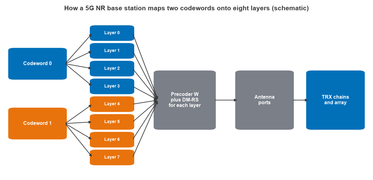
The precoder then maps layers to ports. NR leaves much of this to the implementation: because each layer carries its own DM-RS through the same precoder, the device estimates an effective channel without having to know the precoder used.
NR standards values for MIMO layers
The table gives the main values in the specifications. Devices support only part of these, and capability signalling sets the actual limit.
| Item | Value | Where it is defined |
|---|---|---|
| PDSCH layers per device | Up to 8 | TS 38.211, TS 38.214 |
| Codewords | 1 for 1 to 4 layers, 2 for 5 to 8 layers | TS 38.211, Table 7.3.1.3-1 |
| PUSCH layers per device | Up to 4 in earlier releases, up to 8 with Release 18 for 8-transmit devices | TS 38.211, TS 38.214 |
| DM-RS type 1 ports | 4 single-symbol, 8 double-symbol | TS 38.211 |
| DM-RS type 2 ports | 6 single-symbol, 12 double-symbol | TS 38.211 |
| Release 18 DM-RS | Up to 24 orthogonal ports for MU-MIMO | Release 18 enhancement |
| CSI-RS ports for codebook reporting | Up to 32, with Release 19 reaching 128 by combining CSI-RS resources | TS 38.214 |
| Type II codebook rank | Up to 2, or up to 4 for enhanced Type II in Release 16 | TS 38.214 |
DM-RS: how a device separates the layers
Each layer needs an orthogonal demodulation reference signal. NR combines frequency combs with code division. Within one code division multiplexing (CDM) group, ports share the same resource elements and are separated by orthogonal cover codes. Different CDM groups occupy different subcarriers.
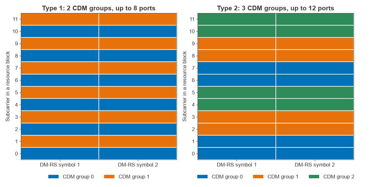
Figure 2 compares the two configurations. Type 1 alternates two groups on every other subcarrier, with six elements per group per symbol. Type 2 uses three groups of adjacent subcarrier pairs, with four elements per group per symbol. Type 1 has a denser pattern and so tolerates more frequency selectivity. Type 2 supports more ports, which is useful for multi-user operation.
More layers cost more overhead. A slot holds 168 resource elements per resource block. Four layers on type 1 single-symbol DM-RS need both CDM groups, which takes the 12 elements of one symbol, or 7.1%. Eight layers need double-symbol DM-RS, taking 24 elements, or 14.3%. Additional DM-RS positions for high mobility raise these numbers further.
Channel state information and rank adaptation in 5G
The base station needs to know how many layers the channel will support, and in which directions. On FDD carriers the device must report this. The base station sends CSI-RS, and the device returns a CSI report as described in channel state information:
- RI, the rank indicator, is the number of layers the device recommends.
- PMI, the precoding matrix indicator, selects a precoder from a codebook.
- CQI, the channel quality indicator, states the modulation and coding the device expects to support.
Type I and Type II codebooks
Type I codebooks give coarse beam selection and co-phasing with low feedback, and they extend to eight layers when enough ports are configured. Type II codebooks describe each layer as a weighted combination of several beams, which gives much finer spatial detail and so better multi-user separation. The specified limit reflects that cost: a device reports a rank of no more than 2 with Type II, and no more than 4 with enhanced Type II. High-rank single-user links and fine-grained multi-user links are therefore competing goals in FDD.
TDD reciprocity and SRS
On TDD carriers such as the 3.5 GHz band, uplink and downlink share a frequency. The device transmits a sounding reference signal (SRS), and the base station estimates the channel directly. The calibrated array can then calculate its own precoder without a codebook, which suits massive MIMO. Accuracy depends on calibrating the transmit and receive chains, and on how many device antennas can be sounded, since many handsets transmit on fewer antennas than they receive on.
Worked example: peak rate against layers
TS 38.306 gives an approximate maximum data rate for one carrier:
Rate = v × Qm × f × Rmax × (NPRB × 12 / Ts) × (1 − OH)
Here v is the number of layers, Qm the modulation order, f a scaling factor, and Rmax = 948/1024. Ts = 10-3 / (14 × 2μ) s is the average symbol time, and OH is an overhead of 0.14 for FR1 downlink, 0.18 for FR2 downlink, 0.08 for FR1 uplink and 0.10 for FR2 uplink.
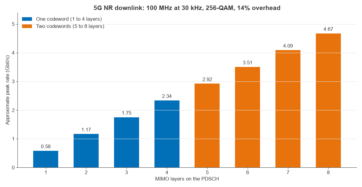
Take 100 MHz in FR1 at 30 kHz spacing (μ = 1), which gives 273 resource blocks. With 256-QAM (Qm = 8) and f = 1:
- Ts = 35.7 µs and NPRB × 12 = 3,276 subcarriers, or 91.7 million resource elements per second.
- One layer: 8 × 0.926 × 91.7 M × 0.86 = 584 Mbit/s.
- Four layers: 2.34 Gbit/s. Eight layers: 4.67 Gbit/s, as Figure 3 shows.
- With 75% of TDD slots on the downlink, a typical kind of allocation, four layers fall to about 1.75 Gbit/s.
- Two uplink layers on the same carrier, with OH = 0.08, give 1.25 Gbit/s before any TDD share.
Peak numbers assume every layer supports the top modulation. Real layers do not. Doubling layers also splits the transmit power, which lowers SNR per layer by 3 dB. If a two-layer link has 20 dB per layer, then an ideal four-layer link has 17 dB per layer. The Shannon totals are 13.3 and 22.7 bit/s/Hz, so doubling layers gives a factor of 1.7 and not 2, even with four equally strong layers. MIMO capacity treats the general case. This is why the RI report changes constantly, and why many links run below their device maximum.
SU-MIMO, MU-MIMO and beams in deployed NR
Single-user MIMO sends all layers to one device. Multi-user MIMO sends layers to several devices at once, separated by precoding. A handset typically has four receive antennas in the mid-band, which caps single-user rank at four, but a 64-transceiver array can serve more total layers by pairing devices with distinct spatial signatures. The up-to-12 orthogonal DM-RS ports of type 2, and 24 in Release 18, exist for that purpose.
Frequency changes the picture. In FR1 the channel is often rich in scattering, so rank 3 or 4 is achievable. In FR2, analog beamforming concentrates energy along a few paths, and two layers on orthogonal polarizations are the typical arrangement. Array hardware is covered in MIMO, beamforming and phased arrays, and the wider radio design in the 5G RF front end.
Layers also set linearity limits. Each stream’s error vector adds to inter-layer leakage, and high-rank 256-QAM needs a low error vector magnitude from every chain, as explained in modulation, EVM and PAPR.
Frequently asked questions
How many layers does 5G NR support?
The PDSCH supports up to eight layers for one device. The PUSCH supported up to four layers in earlier releases, and Release 18 extends this to eight for devices with eight transmit chains. Actual device capability is usually lower, with four downlink layers common in mid-band handsets.
How does 5G spatial multiplexing differ from LTE?
LTE also reached eight downlink layers in later releases. NR has more flexible DM-RS configurations, supports 32 CSI-RS ports and high-resolution Type II feedback from its first release, and is built around beam management, which together make massive MIMO and multi-user operation more practical.
What is the difference between a layer and a codeword in 5G?
A layer is a spatial stream. A codeword is a coded block of data. One codeword is mapped across one to four layers, and transmissions of five to eight layers use two codewords.
Does spatial multiplexing work at mmWave in 5G?
Yes, but typically with fewer layers. Sparse propagation and analog beamforming usually limit a link to two layers, one on each polarization.
Related topics
More on the antenna side appears in multiple antenna systems, and the radio architectures series places these chains in a full radio.