


Phase shift keying (PSK) is a digital modulation method that encodes data in the phase of a constant-amplitude carrier, using two states for BPSK, four for QPSK and eight for 8-PSK. A receiver detects it by comparing the received phase with a recovered carrier, or with the previous symbol in differential PSK. At an uncoded BER of 10−5, coherent BPSK and QPSK need an Eb/N0 of about 9.6 dB.
PSK is the digital form of phase modulation, and it sits alongside the other digital modulation techniques as the usual choice when range matters more than rate.
PSK Principles: Mapping Bits to Phase
An M-PSK symbol has fixed amplitude and one of M equally spaced phases:
sm(t) = A cos(2πfct + φm), with φm = 2πm/M
Equivalently, the symbols sit evenly around a circle in the IQ plane. Each carries log2M bits, and the distance between neighbours for unit-energy symbols is dmin = 2 sin(π/M).
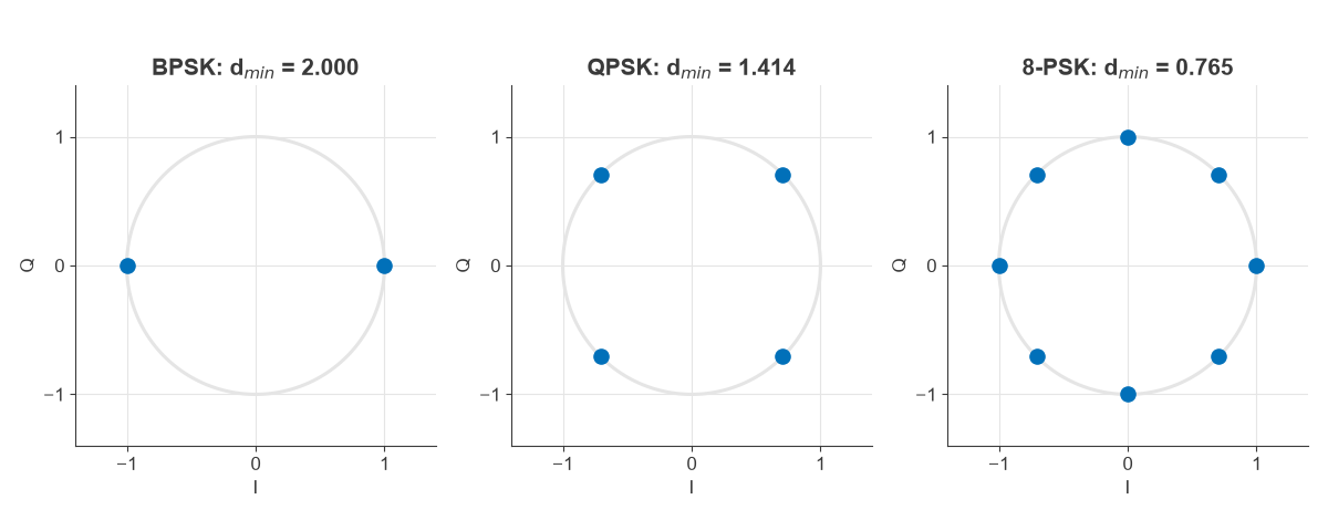
BPSK, QPSK and Higher-Order PSK
Binary phase shift keying
BPSK uses phases 0 and 180 degrees, so the carrier is simply multiplied by ±1. It has the largest possible distance for its energy and one bit per symbol. It is common in low-rate preambles and spread-spectrum links.
Quadrature phase shift keying
QPSK adds a second BPSK signal on the quadrature carrier. Each of the two bits sees the same noise and energy as a BPSK bit, so it needs the same Eb/N0 for twice the spectral efficiency. Its transitions can pass through zero amplitude once pulse shaping is applied, and variants such as offset QPSK and π/4-QPSK limit those transitions to ease the demand on the amplifier.
8-PSK and beyond
8-PSK fits three bits per symbol on the ring, and 16-PSK four. As the table shows, the ring runs out of room quickly. At four bits per symbol, QAM is the better arrangement, which is why PSK stops at low orders in most systems.
| Scheme | Bits per symbol | dmin | Eb/N0 for BER 10−5 (dB) | Penalty against BPSK (dB) |
|---|---|---|---|---|
| BPSK / QPSK | 1 / 2 | 2.000 / 1.414 | 9.59 | 0 |
| DBPSK | 1 | n/a | 10.34 | 0.75 |
| 8-PSK | 3 | 0.765 | 12.97 | 3.38 |
| 16-PSK | 4 | 0.390 | 17.44 | 7.85 |
The constellation has a peak/average ratio of 0 dB, since all points have equal power. Real signals are not quite constant envelope, because pulse shaping filters create amplitude changes between symbols. That still leaves a lower peak/average ratio than QAM, a benefit discussed in Modulation, EVM and PAPR.
PSK Signal Detection
A PSK detector has three jobs: find the carrier phase, find the symbol timing, and decide which phase was sent.
Coherent detection
A coherent receiver mixes the signal down with a locally generated carrier, passes I and Q through matched filters, and samples once per symbol at the point of maximum SNR. The decision is the constellation point closest to the sample, which for PSK means the nearest phase wedge. The matched filter is optimal in AWGN, which is where the BER formulas below come from.
The local carrier must be recovered from the signal itself, because the modulated PSK carrier has no spectral line at fc. A Costas loop or an M-th power loop removes the modulation and drives a phase-locked loop. Both leave a phase ambiguity of 360/M degrees, so the receiver needs a known pilot sequence or differential coding to resolve which rotation is correct.
Differential PSK
Differential PSK encodes data in the phase change between symbols. The receiver multiplies each symbol by the conjugate of the previous one, with no carrier recovery at all. That simplicity has a cost: the reference symbol is noisy too. For binary DPSK, BER = ½ exp(−Eb/N0), and bit errors tend to arrive in pairs because one noisy symbol affects two decisions.
Bit Error Rate of PSK
The AWGN results for Gray-coded PSK are:
- BPSK and QPSK: BER = Q(√(2Eb/N0))
- DBPSK: BER = ½ exp(−Eb/N0)
- M-PSK, M ≥ 8, with k = log2M: BER ≈ (2/k) Q(√(2kEb/N0) sin(π/M))
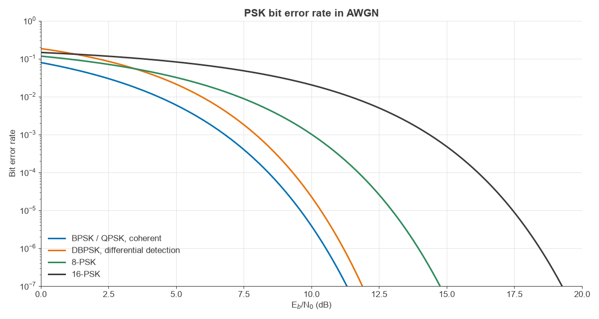
The curves were checked by Monte Carlo simulation. 8-PSK at 12 dB gave 6.7 × 10⁻⁵ against a formula value of 6.3 × 10⁻⁵, a small difference explained partly by the formula ignoring anything beyond nearest neighbours and partly by the limited error count. DBPSK at 8 dB gave 9.6 × 10⁻⁴ against 9.1 × 10⁻⁴, within the scatter expected of paired errors over four million bits. QPSK at 8 dB gave 1.84 × 10⁻⁴ against 1.91 × 10⁻⁴.
Worked Example: Phase Error in a BPSK Receiver
Carrier recovery is never perfect. A static phase error φ reduces the useful component by cos φ, so:
BER = Q(√(2Eb/N0) cos φ)
The equivalent SNR loss is −20log10(cos φ). Take a link operating at Eb/N0 = 9.6 dB.
| Phase error (degrees) | SNR loss (dB) | BER |
|---|---|---|
| 0 | 0 | 9.7 × 10⁻⁶ |
| 10 | 0.13 | 1.3 × 10⁻⁵ |
| 20 | 0.54 | 3.0 × 10⁻⁵ |
| 30 | 1.25 | 1.1 × 10⁻⁴ |
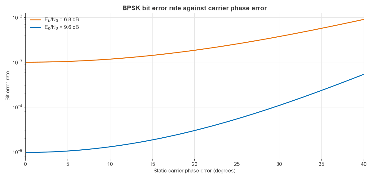
A 10 degree offset barely matters. A 30 degree offset raises the BER about elevenfold. The same thing happens faster for higher orders, since 8-PSK decision wedges are only ±22.5 degrees wide, so a 30 degree error would put every symbol in the wrong wedge with no noise at all.
Worked Example: EVM of a QPSK Signal
Take a QPSK link at Eb/N0 = 8 dB. Then Es/N0 = 8 + 3.01 = 11.01 dB, and if noise is the only impairment:
EVM = 10−11.01/20 = 28.2%
Simulation gave 28.15%. Random phase error behaves the same way. For an RMS phase error of σ radians, EVM ≈ σ when σ is small, so 2 degrees RMS gives 3.49%, a value the simulation and the exact expression both confirmed. QPSK tolerates this easily, with a typical cellular limit of around 17.5%. A dense constellation does not, which is why phase noise is so much more of a design problem for QAM.
PSK Compared with Other Modulation Methods
Against FSK, coherent PSK saves about 3 dB of Eb/N0 and occupies less bandwidth, at the cost of carrier recovery. Against QAM, PSK trades capacity for a lower peak/average ratio, so the transmitter can run closer to saturation, which helps satellite and long-range links. BPSK and QPSK also appear on OFDM subcarriers for control channels and the weakest parts of the signal. Actual link range follows from the RF link budget.
Frequently asked questions
What is the difference between BPSK and QPSK?
BPSK uses two phases and one bit per symbol, while QPSK uses four phases and two bits per symbol. In AWGN their bit error rates match at the same Eb/N0, so QPSK gives twice the data rate in the same bandwidth. QPSK does need 3.01 dB more Es/N0, since each symbol holds two bits.
How is a PSK signal demodulated?
The receiver mixes the signal to baseband with a recovered carrier, applies matched filters to I and Q, samples at the symbol instant and picks the closest phase. A Costas loop is a common way to recover the carrier. Differential PSK skips recovery by comparing consecutive symbols, at a small SNR cost.
Is PSK a type of phase modulation?
Yes. PSK is phase modulation with a discrete message: the phase jumps between fixed values instead of following a continuous signal. Pulse shaping then smooths those jumps to control the bandwidth.
Why does differential PSK perform worse than coherent PSK?
Differential detection uses the previous symbol as its phase reference, and that symbol is as noisy as the current one. For binary signalling the penalty is about 0.75 dB at a BER of 10−5, and it is larger for higher orders.
Related topics
See phase modulation for the analog foundation, QAM for the next step up in order, and the digital modulation overview for the comparison across families. SNR and Eb/N0 explains the units used here, and IQ modulators and demodulators covers the hardware.