


Amplitude modulation (AM) is a modulation method that varies the amplitude of a radio frequency carrier in step with a message signal, while the carrier frequency stays fixed. The result is a carrier plus two sidebands, so an AM signal occupies twice the highest message frequency. A receiver can recover the message from the outline of the waveform, called the envelope, which is what makes AM so simple to demodulate.
What Is Amplitude Modulation?
Modulation places a low frequency message onto a much higher carrier that an antenna can radiate efficiently. AM does this with the carrier’s amplitude. Frequency modulation and phase modulation alter the angle of the carrier instead, and a keyed carrier, described in continuous wave modulation, is the simplest amplitude-varied signal of all.
Voice transmission by AM dates from experiments in the early 1900s, and AM broadcasting spread during the 1920s. Its appeal then is the same as now: a working receiver can be built from a tuned circuit and a diode.
How Does Amplitude Modulation Work?
An AM modulator multiplies the carrier by a term that follows the message. Three signals are involved:
- The message or modulating signal, m(t), such as audio at frequency fm.
- The carrier, Ac cos(2πfct), usually thousands of times higher in frequency.
- The modulated signal, whose envelope traces the message.
The AM modulation formula
For a single tone, the AM signal is:
s(t) = Ac [1 + m cos(2πfmt)] cos(2πfct)
Here m is the modulation index. The bracket is the envelope, and it stays positive while m is 1 or less. Expanding the product with a trigonometric identity separates the three components:
s(t) = Ac cos(2πfct) + (mAc/2) cos(2π(fc + fm)t) + (mAc/2) cos(2π(fc − fm)t)
The first term is the unchanged carrier. The other two are the upper and lower sidebands, and they hold all the information.
Modulation Index in Amplitude Modulation
The modulation index, also called modulation depth when given as a percentage, compares the message amplitude with the carrier amplitude. On an oscilloscope it is read from the envelope maximum and minimum:
m = (Vmax − Vmin) / (Vmax + Vmin)
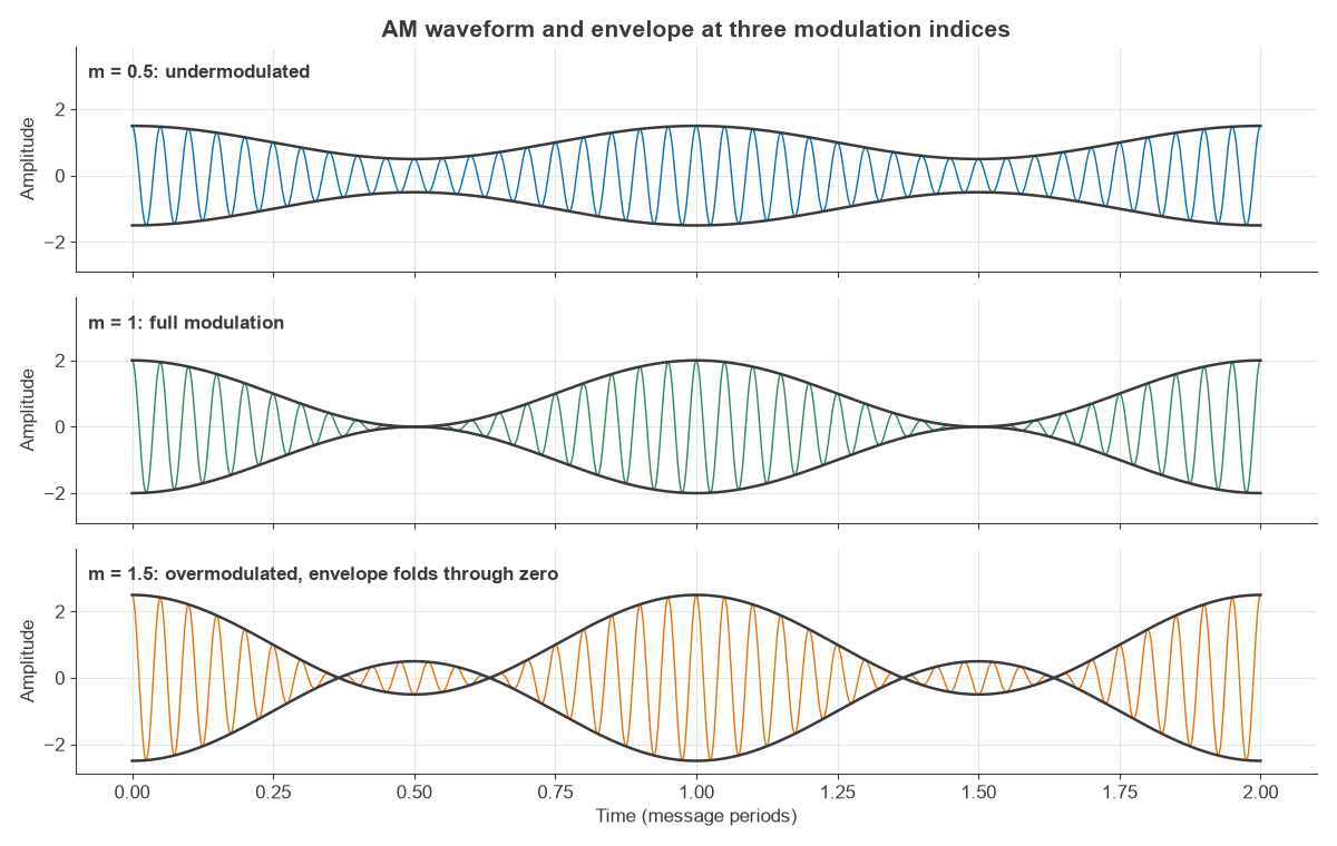
Undermodulation, full modulation and overmodulation
Below m = 1 the signal is undermodulated: the envelope is a clean copy of the message, but less power goes into the sidebands. At m = 1 the envelope just touches zero. Above m = 1 the signal is overmodulated. The envelope folds through zero, and an envelope detector can no longer follow the message. A real transmitter cannot follow the fold, so it clips, and that distortion produces extra sidebands that spread into adjacent channels. Broadcast transmitters therefore use limiters to hold negative peaks below 100%.
When a message contains several tones, the indices combine as a root sum of squares. Tones with indices of 0.5, 0.3 and 0.4 give a total of 0.71.
AM Spectrum and Bandwidth
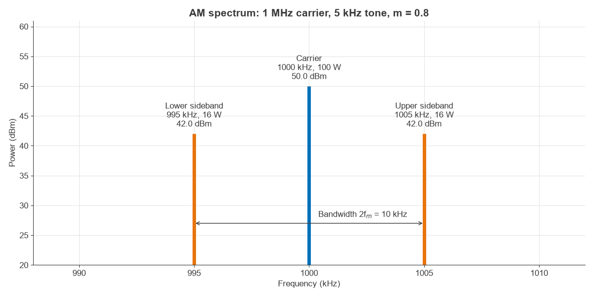
Figure 2 shows the frequency spectrum of a single-tone AM signal. The sidebands sit fm either side of the carrier, so:
Bandwidth = 2fm
For real audio, each tone produces its own pair, and the upper and lower sidebands become mirror images of the audio spectrum. The bandwidth is twice the highest audio frequency. Medium wave broadcast channels are typically spaced 9 or 10 kHz apart depending on region, which limits usable audio to around 4.5 to 5 kHz in a strictly protected channel.
Worked Example: Power in an AM Signal
Take a 1 MHz carrier of 100 V peak into 50 Ω, modulated by a 5 kHz tone at m = 0.8.
- Carrier power: Pc = Ac2 / 2R = 1002 / 100 = 100 W, or 50.0 dBm.
- Sideband amplitude: mAc/2 = 40 V each, which is 8.0 dB below the carrier.
- Power in each sideband: (m2/4) Pc = 16 W, or 42.0 dBm.
- Total power: Pt = Pc(1 + m2/2) = 132 W, or 51.2 dBm.
- Bandwidth: 2 × 5 kHz = 10 kHz, from 995 to 1005 kHz.
- Envelope: Vmax = 180 V and Vmin = 20 V, and (180 − 20)/(180 + 20) = 0.8 as expected.
- Peak envelope power: (1 + m)2 Pc = 324 W, which is 3.9 dB above the average of 132 W.
- RMS current: rises from 1.41 A unmodulated to 1.62 A modulated, a factor of 1.15.
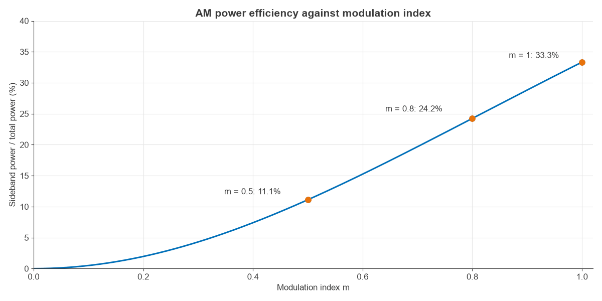
That peak figure matters for RF amplifier design, because the output stage must stay linear up to 324 W even though the average is 132 W. Only 32 W of the 132 W, or 24.2%, carries the message.
Why AM is power hungry
The share of power in the sidebands is:
η = m2 / (2 + m2)
Even at m = 1 this reaches only 33.3%, as Figure 3 shows. Speech has a low average modulation index, so the real figure is far smaller. The rest of the power goes into a carrier that conveys nothing, although it does give the receiver a reference for detection.
Types of Amplitude Modulation
The carrier and one sideband are both redundant in a strict sense, and the types of AM differ in what they keep.
| Type | What is transmitted | Bandwidth | Typical use |
|---|---|---|---|
| DSB-FC (standard AM) | Carrier and both sidebands | 2fm | Broadcasting, airband voice |
| DSB-SC | Both sidebands, no carrier | 2fm | Stereo subcarriers, building block of I/Q modulators |
| SSB | One sideband | fm | HF voice, amateur and marine radio |
| VSB | One sideband plus a trace of the other | Slightly over fm | Analog television |
Digital schemes extend the same idea. Amplitude shift keying uses discrete amplitude levels, and QAM sends two amplitude-modulated carriers in quadrature.
AM Modulators and the AM Transmitter
An AM modulator needs a nonlinear or multiplying element to create the sum and difference frequencies. A mixer does this directly. Transmitters fall into two groups:
- Low-level modulation applies the message at a small signal stage, then amplifies the AM signal with linear amplifiers. It is simple but the linear chain is inefficient.
- High-level modulation varies the supply of an efficient final stage. The message source must then supply the sideband power, which is at least 32 W in the worked example, and more once the final stage’s own losses are included.
Modern solid state broadcast transmitters often use switching techniques that behave like high-level modulation at much better efficiency.
AM Demodulation: Envelope and Synchronous Detection
An envelope detector uses a diode followed by an RC filter. The capacitor follows the peaks of the carrier but must still track the message, so:
1/fc ≪ RC ≪ 1/fm
If RC is too long the output cannot fall as quickly as the envelope, which is called diagonal clipping. For a single tone, avoiding it requires RC ≤ √(1 − m2) / (2πfmm). With m = 0.8 and fm = 5 kHz, that limit is 23.9 µs. A value of 10 µs, such as 10 kΩ with 1 nF, sits comfortably between the limit and the 1 µs carrier period.
A synchronous detector instead multiplies the signal by a recovered copy of the carrier. It costs more but works at low signal levels and during overmodulation, and it can also recover DSB-SC and SSB signals, which the envelope detector cannot.
Advantages, Disadvantages and Applications of Amplitude Modulation
The main advantages are simple transmitters and receivers, and narrow bandwidth compared with wideband FM. The main disadvantages are low power efficiency and sensitivity to noise and interference, since most impulsive noise appears directly as amplitude variation. Selective fading can also damage the carrier and sidebands unequally, which distorts the output of an envelope detector.
AM remains in use for long, medium and short wave broadcasting, where a signal can cover a wide area by ground wave or ionospheric propagation. Aeronautical VHF voice uses AM at around 118 to 137 MHz, partly because overlapping transmissions stay audible rather than one capturing the receiver. Citizens band radio and some navigation aids use it too.
Frequently asked questions
What is amplitude modulation in simple terms?
Amplitude modulation changes the strength of a radio carrier in step with a message such as speech. The carrier frequency does not change. A receiver recovers the message by tracking the outline of the signal.
What is the modulation index of AM?
It is the ratio of message amplitude to carrier amplitude, and it can be measured as (Vmax − Vmin) / (Vmax + Vmin). A value of 1, or 100%, is full modulation. Higher values cause envelope distortion and adjacent channel splatter.
What is the bandwidth of an AM signal?
Standard AM needs twice the highest message frequency. Audio limited to 5 kHz therefore needs 10 kHz. SSB cuts this in half by sending one sideband only.
What is the difference between AM and FM?
AM carries the message in the carrier’s amplitude, while FM carries it in the instantaneous frequency. FM has a constant envelope, so it can use efficient saturated amplifiers and reject amplitude noise, but broadcast FM needs far more bandwidth, about 180 kHz against 10 kHz.
Related topics
For the wider picture, see digital modulation techniques and RF fundamentals. Power and level measurements are covered in measuring amplitude and power in RF signals, and the sidebands above can be observed with the methods in spectrum analyzer basics.