

MIMO precoding is the processing a transmitter applies across its antennas before sending, so that each stream reaches its intended receiver with the best possible SNR and the least interference. It multiplies the data symbols by a matrix W chosen from channel state information. In multi-user MIMO, precoding is what lets a base station serve several users at once on the same frequency.
The spatial multiplexing article covers the single-user case with SVD. This page concentrates on the precoder itself: the linear designs, their multi-user performance, non-linear options, and what they need from the hardware and from CSI.
What is MIMO precoding?
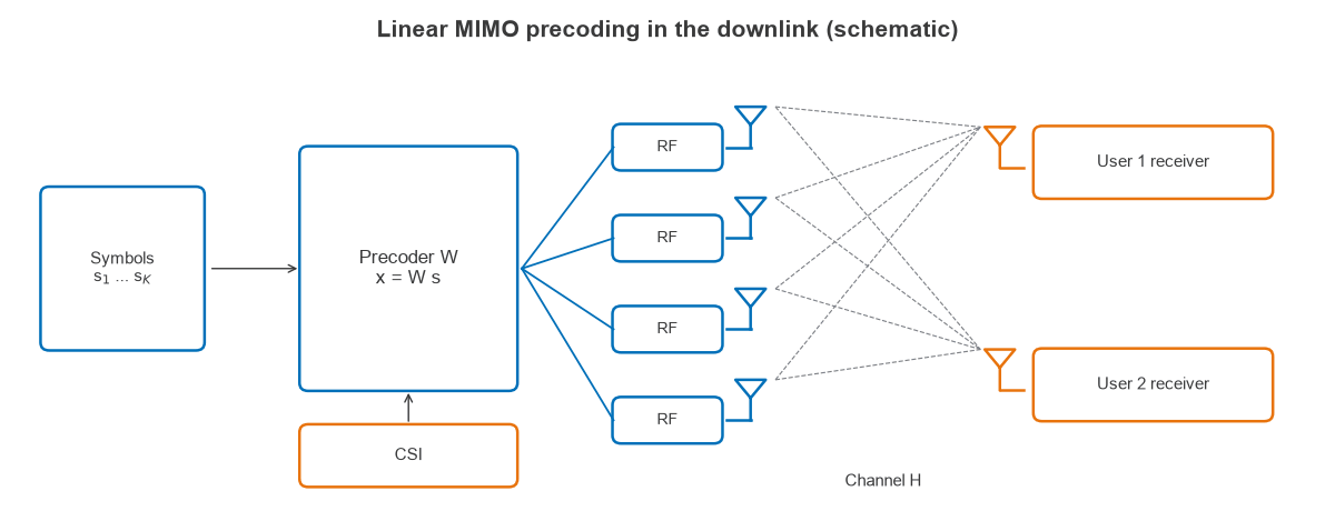
With K data symbols in vector s and Nt transmit antennas, a linear precoder forms the transmitted vector:
x = W s, with ||W||F2 = 1 for fixed total power
Each column of W is the antenna weighting for one stream. The signal received by single-antenna user k is:
yk = hkwksk + Σj≠k hkwjsj + nk
The second term is inter-user interference. Precoding balances that term against the wanted signal power, and the users’ receivers play no part. This is the major difference from receive processing, since single-antenna users cannot separate streams themselves.
Single-user and multi-user precoding
In single-user MIMO, the ideal precoder uses the right singular vectors of the channel, V from H = UΣVH. The receiver applies UH and the channel splits into parallel paths. Spatial multiplexing works through this with numbers.
Multi-user MIMO differs because the users cannot cooperate, so no UH exists across them. All of the interference has to be handled at the transmitter. The rest of this page takes that harder case, with a channel matrix H whose rows are the users’ channel vectors.
Linear precoding techniques
Three designs cover most practical systems. With ρ as total transmit SNR:
| Precoder | Weights (before power scaling) | Aim | Weakness |
|---|---|---|---|
| Maximum ratio transmission (MRT) | W = HH | Maximise signal at each user | Ignores interference |
| Zero forcing (ZF) | W = HH(H HH)-1 | Remove all interference | Wastes power on poor channels |
| Regularised ZF (RZF), or MMSE | W = HH(H HH + (K/ρ) I)-1 | Balance both | Needs the SNR |
RZF moves between the other two. As ρ falls, the K/ρ term dominates and RZF tends to MRT. As ρ rises, it tends to ZF. The weighting used here is the common choice for equal-power users, and it is also often called the MMSE or Wiener precoder.
Worked example: a two-user precoder
Take a base station with two antennas serving two single-antenna users through the real channel H = [1, 0.6; 0.6, 1]. The channel has singular values of 1.6 and 0.4, so a condition number of 4. Total transmit SNR is 20 dB, which is ρ = 100, and W is scaled to unit Frobenius norm.
The ZF precoder is W = [0.606, -0.364; -0.364, 0.606]. For user 1, the wanted gain is 1 × 0.606 + 0.6 × (-0.364) = 0.388, and the interference is 1 × (-0.364) + 0.6 × 0.606 = 0, as intended. The SINR is 100 × 0.3882 = 15.1, or 11.8 dB, for each user.
Without the other user, MRT toward user 1 alone gives 100 × 1.36 = 136, or 21.3 dB. Part of the 9.5 dB difference is the power split between two users, and the rest is the cost of steering away from the other user’s channel, which is well aligned with the first user’s.
| Scheme | SINR per user at 20 dB | Sum rate at 0 dB | Sum rate at 10 dB | Sum rate at 20 dB |
|---|---|---|---|---|
| MRT | 1.0 dB | 1.06 b/s/Hz | 2.11 b/s/Hz | 2.35 b/s/Hz |
| Zero forcing | 11.8 dB | 0.40 b/s/Hz | 2.65 b/s/Hz | 8.01 b/s/Hz |
| RZF | 12.0 dB | 1.10 b/s/Hz | 3.34 b/s/Hz | 8.15 b/s/Hz |
| One user at a time, MRT | 21.3 dB (one user) | 1.24 b/s/Hz | 3.87 b/s/Hz | 7.10 b/s/Hz |
The last row is a useful reality check. At 0 and 10 dB, serving one user at a time beats all three precoders in this poorly conditioned channel. At 20 dB, serving both pays off, with 8.15 b/s/Hz against 7.10 b/s/Hz. A real scheduler makes this choice continually, and it pairs users whose channels are close to orthogonal.
How antenna count changes MIMO precoding
The gain from precoding depends on spare spatial dimensions. Figure 2 shows Monte Carlo results for four users in i.i.d. Rayleigh fading, averaged over 1,500 channels, with 8 and then 4 base station antennas.
| Antennas, SNR | MRT | Zero forcing | RZF |
|---|---|---|---|
| 8 antennas, 0 dB | 4.45 b/s/Hz | 4.23 b/s/Hz | 5.22 b/s/Hz |
| 8 antennas, 20 dB | 8.20 b/s/Hz | 26.94 b/s/Hz | 26.99 b/s/Hz |
| 4 antennas, 10 dB | 4.81 b/s/Hz | 5.07 b/s/Hz | 8.24 b/s/Hz |
| 4 antennas, 20 dB | 5.35 b/s/Hz | 14.71 b/s/Hz | 16.21 b/s/Hz |
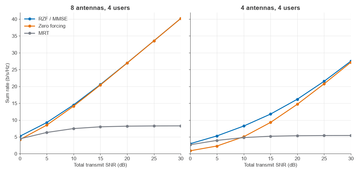
MRT saturates in both cases because raising power raises interference equally, leaving a floor near 8.3 b/s/Hz with 8 antennas and 5.5 b/s/Hz with 4. With 8 antennas, the channel is well conditioned and ZF is close to RZF from 15 dB upward. With 4 antennas, H is square and often nearly singular, so ZF is much worse than RZF until high SNR. Twice as many antennas as users is therefore a comfortable margin for linear precoding, and large arrays push further in that direction.
Non-linear precoding
Non-linear precoders can beat the linear ones when users’ channels are strongly aligned.
- Dirty paper coding (DPC) pre-subtracts interference that is known to the transmitter, and it achieves the capacity of the MIMO downlink. It is a theoretical benchmark and is not used directly because of its complexity.
- Tomlinson-Harashima precoding (THP) is a practical approach to the same idea. It subtracts interference user by user and applies a modulo operation to keep power bounded. The modulo step costs a precoding loss of about M/(M-1) for M-QAM: 1.25 dB for QPSK, 0.28 dB for 16-QAM and 0.07 dB for 64-QAM.
- Vector perturbation adds a chosen integer offset to the symbols to reduce transmit power. It performs well but needs a search over a lattice.
Block diagonalisation for multi-antenna users
If each user has several antennas, ZF per antenna is wasteful, because it blocks a user’s own antennas from each other. Block diagonalisation nulls interference only between users, then leaves each user an interference-free MIMO channel that can be precoded with its own SVD. Spatial streams per user follow from the rank of that residual channel.
Effect of CSI errors on precoding
Multi-user precoding is far more sensitive to CSI errors than single-user beamforming, because a null is a precise cancellation. To model this, the transmitter sees a noisy version of H with a given error variance, while the true H is used to measure the rates. The figures below are RZF with 8 antennas and 4 users.
| Sum rate at SNR | Perfect CSI | Error variance 0.01 | Error variance 0.1 |
|---|---|---|---|
| 10 dB | 14.5 b/s/Hz | 14.1 b/s/Hz | 11.5 b/s/Hz |
| 20 dB | 27.0 b/s/Hz | 24.0 b/s/Hz | 15.5 b/s/Hz |
| 30 dB | 40.2 b/s/Hz | 28.8 b/s/Hz | 16.4 b/s/Hz |
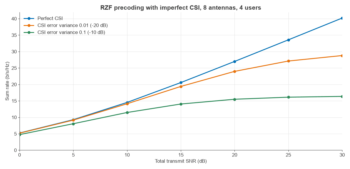
At 30 dB, an error variance of 0.1 removes 59% of the sum rate, and the curve has flattened. As a rule, CSI quality must improve along with SNR for precoding gains to continue. Channel state information covers how that CSI is measured, and how it ages.
Codebook precoding and limited feedback
In FDD systems, the receiver usually picks the best precoder from a shared codebook and returns only the index, in b bits. With a random vector codebook, the average beamforming loss for Nt antennas is about 10 log10(1 – 2-b/(Nt-1)) dB. Monte Carlo results for 4 antennas with 4,000 channels show this is a little pessimistic at low b.
| Feedback bits | Formula | Monte Carlo |
|---|---|---|
| 2 | -4.32 dB | -3.36 dB |
| 4 | -2.20 dB | -1.88 dB |
| 6 | -1.25 dB | -1.08 dB |
| 8 | -0.74 dB | -0.66 dB |
Each two bits buy less than the last, which is why single-user codebooks can stay small. Multi-user precoding needs more bits, since quantisation error turns into interference, the effect shown in Figure 3.
Hardware and RF requirements
Precoding has several consequences for the RF design:
- Per-antenna power: the formulas above limit total power, but each PA has its own limit. Weights that load one antenna heavily have to be scaled down, or the power constraint must be built into the design.
- Chain calibration: relative gain and phase between chains must be known, or calibrated out. An uncalibrated error acts like a CSI error.
- Linearity: PA distortion is a form of noise that follows the signal, so linearisation and EVM limits matter for high-order streams.
- Wideband weights: OFDM systems compute W per subcarrier or per group of subcarriers, which is simple in digital precoding. Hybrid arrays at millimetre-wave frequencies combine a small digital precoder with analog phase shifters, as described in MIMO, Beamforming and Phased-Array Architectures.
Frequently asked questions
What is the difference between precoding and beamforming?
Beamforming usually means sending one stream with phased weights, for maximum gain toward one receiver. Precoding is the general term for any transmit matrix, including several streams and several users. Single-stream beamforming is a special case of precoding.
Does precoding need channel state information?
Yes, at least in part. Non-codebook methods need the channel itself, from feedback or TDD reciprocity. Codebook methods need only an index chosen by the receiver. Open-loop schemes without CSI exist, but they provide diversity and not interference management.
Which precoder is best for multi-user MIMO?
RZF is the usual choice among the linear options, since it matches or beats MRT and ZF at all SNRs in the results above. ZF is close when antennas clearly outnumber users and SNR is high. MRT suits very large arrays at low SNR, where simplicity counts for most.
How many users can a base station precode for?
With linear precoding, the limit is the number of transmit antennas, since each stream needs its own spatial dimension. Performance is better well below this limit, as the 8-antenna and 4-antenna results show for four users.
Related topics
Continue with spatial multiplexing for SVD and receivers, beamforming for array behaviour, and channel state information for estimation and feedback. The basics are in MIMO and multiple antenna systems, with modulation and EVM and the RF design hub for more detail.