


Waveform frequency is the number of times a repeating waveform completes its cycle each second, measured in hertz, and it equals one divided by the period. A sine wave contains that one frequency only, while square, triangle and sawtooth waveforms also contain harmonics at whole multiples of it. Shape therefore decides which frequencies a waveform really occupies, which is why RF engineers look at signals in both time and frequency.
What Is Waveform Frequency?
A waveform is a plot of a signal’s voltage, current or field strength against time. If the shape repeats every T seconds, its frequency is:
f = 1 / T
For radio signals, the same frequency also fixes the wavelength in free space, λ = c / f, where c is about 3 × 10⁸ m/s. A table of round values gives a feel for the scale:
| Frequency | Period | Wavelength | Example |
|---|---|---|---|
| 1 MHz | 1 µs | 300 m | Medium wave radio |
| 100 MHz | 10 ns | 3 m | VHF FM broadcast |
| 2.4 GHz | 417 ps | 12.5 cm | Wi-Fi and Bluetooth |
| 28 GHz | 35.7 ps | 1.07 cm | Millimeter wave 5G |
Amplitude, phase and shape are independent of frequency. Doubling the amplitude of a 100 MHz sine wave leaves its frequency unchanged, and so does shifting it in time.
Types of Waveforms
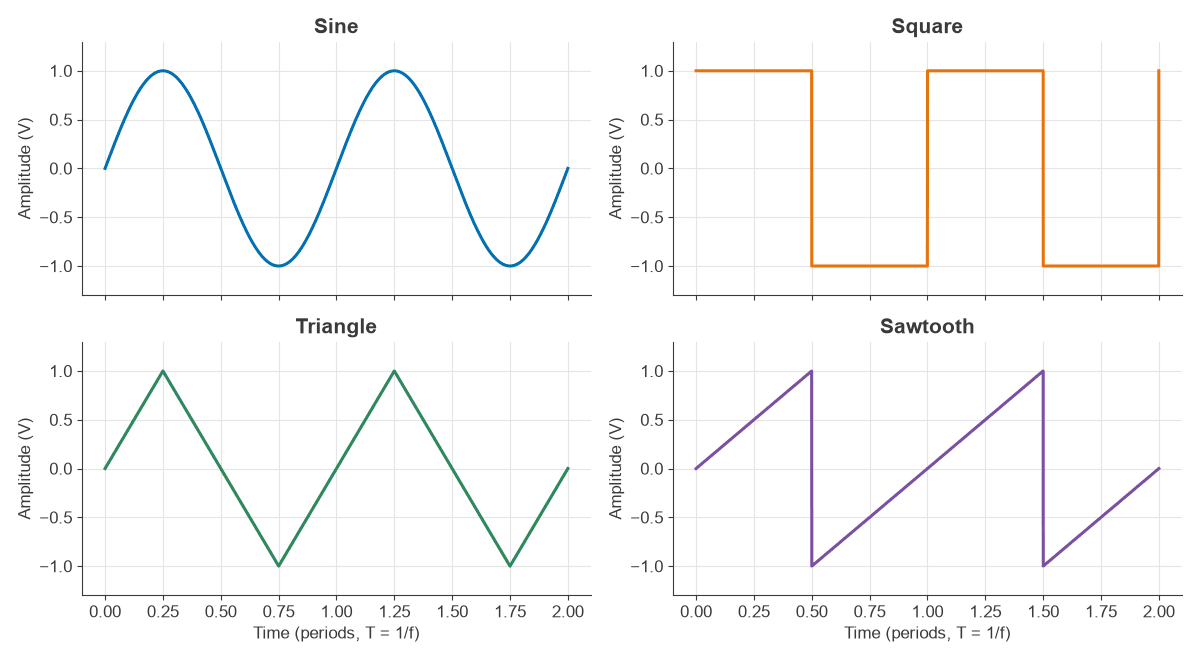
The four classic waveform types are the sine, square, triangle and sawtooth. Each is defined by how it moves between its peaks, and Figure 1 shows them at the same frequency and amplitude.
| Waveform | Harmonics present | Harmonic amplitude | Fundamental share of power | Crest factor |
|---|---|---|---|---|
| Sine | None | Not applicable | 100% | 1.41 |
| Square | Odd only | 1/n | 81.1% | 1.00 |
| Triangle | Odd only | 1/n2 | 98.6% | 1.73 |
| Sawtooth | All | 1/n | 60.8% | 1.73 |
A sine wave is the natural output of an oscillator and the form of a pure radio carrier. Square waves come from digital logic and from switching stages such as mixers driven hard by a local oscillator. Triangle and sawtooth shapes are common in sweep generators and in frequency-swept test signals. Pulse waveforms, a square wave with unequal high and low times, are covered below.
Harmonics: The Frequencies Inside a Waveform
Fourier analysis shows that any repeating waveform is a sum of sine waves at the fundamental frequency f and its multiples 2f, 3f and so on. For a waveform with peak value A:
- Square: (4A/π) × [sin(2πft) + (1/3) sin(6πft) + (1/5) sin(10πft) + …]
- Triangle: (8A/π2) × [sin(2πft) − (1/9) sin(6πft) + (1/25) sin(10πft) − …]
- Sawtooth: (2A/π) × [sin(2πft) − (1/2) sin(4πft) + (1/3) sin(6πft) − …]
Plotted against frequency, these series form the line spectra in Figure 2. In decibels relative to the fundamental (dBc), the third harmonic of a square wave is at −9.5 dBc, while that of a triangle wave is at −19.1 dBc. Sharp corners require high frequency content, so smoother shapes have harmonics that fall away faster.
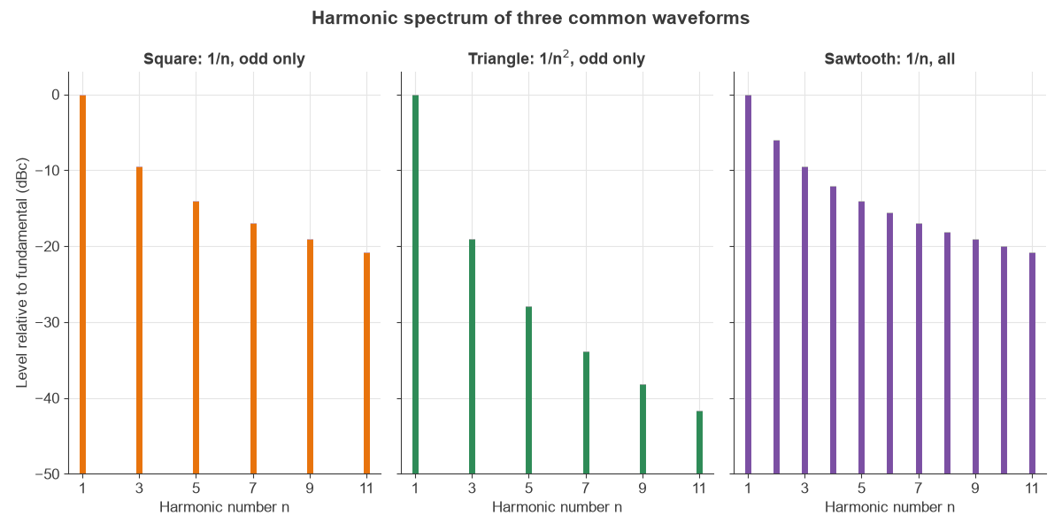
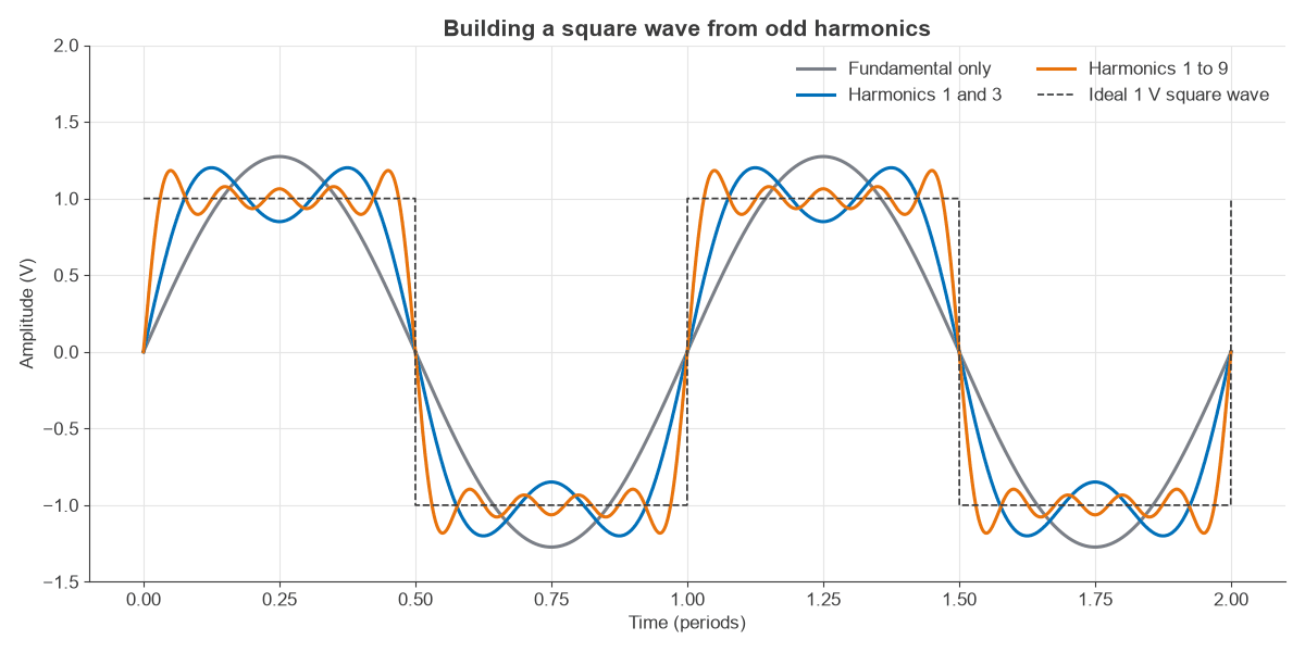
Figure 3 runs the idea in reverse. Adding odd harmonics to a sine wave steadily squares up the shape, and the ripple near each edge is the Gibbs effect, which remains for any finite number of harmonics.
Worked Example: A 10 MHz Square Wave in 50 Ω
Consider a ±1 V square wave at 10 MHz driving a 50 Ω load. Its total power is 12 / 50 = 20 mW, or 13.0 dBm. Each harmonic has a peak voltage of 4/(πn), and its power is V2 / (2R).
| Harmonic n | Frequency | Peak voltage | Power | Level | Relative to fundamental | Cumulative share of power |
|---|---|---|---|---|---|---|
| 1 | 10 MHz | 1.273 V | 16.21 mW | 12.1 dBm | 0 dBc | 81.1% |
| 3 | 30 MHz | 0.424 V | 1.80 mW | 2.6 dBm | −9.5 dBc | 90.1% |
| 5 | 50 MHz | 0.255 V | 0.65 mW | −1.9 dBm | −14.0 dBc | 93.3% |
| 7 | 70 MHz | 0.182 V | 0.33 mW | −4.8 dBm | −16.9 dBc | 95.0% |
| 9 | 90 MHz | 0.141 V | 0.20 mW | −7.0 dBm | −19.1 dBc | 96.0% |
Two results stand out. The fundamental has a peak of 1.27 V, more than the 1 V square wave it came from, and it holds 81% of the power. A square wave used as a clock is also a strong multi-tone source reaching far above its nominal frequency.
To turn this into a clean sine wave, a low-pass RF filter needs to remove the harmonics. A filter giving 40 dB of rejection at 30 MHz would leave the third harmonic at −9.5 − 40 = −49.5 dBc, ignoring any small loss at 10 MHz.
Rise time and bandwidth
Real edges have a finite rise time tr, which rounds off the spectrum. A common estimate of the bandwidth is:
BW ≈ 0.35 / tr
A 3.5 ns edge gives about 100 MHz, so a 10 MHz clock with that edge has meaningful content up to around the tenth harmonic. For a trapezoidal waveform the harmonic envelope falls at 20 dB per decade up to about 1/(πtr), here 91 MHz, then at 40 dB per decade. The same reasoning sets the bandwidth an oscilloscope needs to display an edge faithfully.
Pulse Waveforms and Duty Cycle
A pulse train of amplitude A and duty cycle d has a DC level of Ad, with harmonics of amplitude:
an = 2Ad |sin(πnd) / (πnd)|
For a 1 V pulse train at 25% duty, the DC level is 0.25 V and the first five harmonics are 0.450, 0.318, 0.150, 0 and 0.090 V. Every fourth harmonic vanishes, because the sinc envelope has nulls at multiples of 1/d.
Pulsed radar uses the same result. A 1 µs pulse repeated at 1 kHz has a duty cycle of 0.1%, which is 30 dB between peak and average power. Modulated onto a carrier, its spectrum has lines 1 kHz apart inside a main lobe 2 MHz wide between nulls. Line spacing comes from the repetition frequency, and lobe width comes from the pulse length.
Radio Waveforms
In radio engineering, the term radio waveform or RF waveform usually means more than a shape. It refers to the full definition of a transmitted signal, including its modulation, coding and timing. These waveforms are not periodic in the simple sense, so they occupy a band of frequencies around the carrier rather than a neat set of harmonics.
| RF waveform | What varies | Occupied spectrum |
|---|---|---|
| Continuous wave | Nothing, or on-off keying | A single line, or a very narrow band |
| Amplitude modulation | Carrier amplitude | Carrier and two sidebands, twice the message bandwidth |
| Frequency modulation | Instantaneous frequency | Many sidebands, about 180 kHz for broadcast FM |
| QAM | Amplitude and phase | Close to the symbol rate, set by the pulse filter |
| OFDM | Many subcarriers at once | A flat block of many narrow subcarriers |
| Chirp | Frequency sweeps during the pulse | About the swept range, used in radar |
In waveform communication systems, the choice of waveform decides how well a link copes with noise, multipath and amplifier limits. A waveform with a high peak-to-average ratio, for example, needs more back-off in the power amplifier, as described in modulation, EVM and PAPR.
A nominally sine output can also grow harmonics of its own. Any nonlinear stage creates them, as explained in harmonic distortion and AM/PM.
Measuring Waveform Frequency
An oscilloscope shows the waveform in the time domain, so frequency comes from the measured period and the shape can be seen directly. A frequency counter gives the most precise reading for a single dominant tone. A spectrum analyzer shows the frequency domain, where small harmonics such as a −50 dBc third harmonic are easy to measure even though they would be invisible on a scope.
Frequently asked questions
What is the relationship between waveform and frequency?
Frequency tells how often a waveform repeats, and the shape tells which harmonics of that frequency are present. Two waveforms at 10 MHz share a fundamental but can have very different spectra.
What are the main types of waveforms?
The common types are sine, square, triangle, sawtooth and pulse waveforms. In radio, modulated signals such as AM, FM, QAM and OFDM are also called waveforms.
Does a high frequency waveform have a shorter wavelength?
Yes. Wavelength is c/f, so raising the frequency shortens it in proportion. A 100 MHz signal has a 3 m wavelength in free space, and a 2.4 GHz signal has a 12.5 cm wavelength.
Why is a sine wave used for radio carriers?
A sine wave holds all of its power at one frequency, so it stays inside its allotted channel and does not interfere with others. Other shapes would radiate harmonics that need filtering.
Related topics
For more background, see RF fundamentals and measuring amplitude and power in RF signals. Oscillators, filters and modulators are covered in RF design, and receiver structures in the Radio Architectures series.