

The importance of frequency in RF communication comes from what it decides: wavelength, antenna size, path loss, propagation mode and the bandwidth available. Lower frequencies travel farther and penetrate buildings better with smaller loss between fixed-gain antennas. Higher frequencies offer far more bandwidth and allow narrow beams from small antennas, at the cost of range and harder hardware.
RF communication means carrying information on electromagnetic waves, from a few kHz to beyond 100 GHz. Almost every design decision starts with the carrier frequency, and this article shows the effect with numbers. For related definitions, see the relationship between frequency and wavelength and frequency bands in RF design.
What Frequency Means in RF Communication
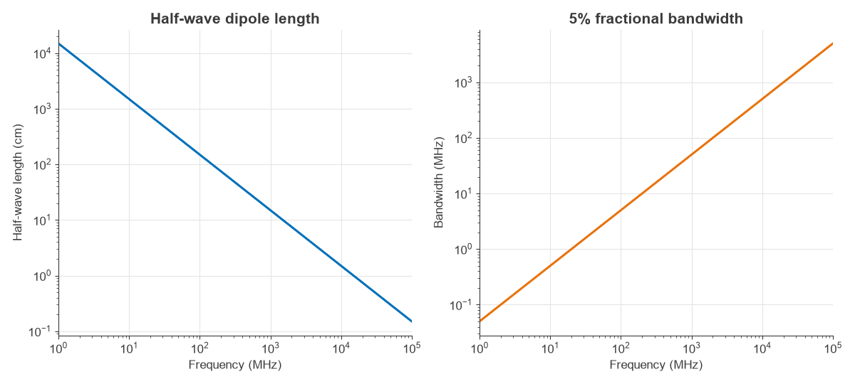
Frequency is the number of carrier cycles per second, measured in hertz. It is not the data rate. Information is added by modulating the carrier, and data rate depends on bandwidth and SNR. Frequency sets the wavelength through λ = c/f:
| Frequency | Wavelength | Half-wave length | FSPL at 1 km | Doppler at 30 m/s |
|---|---|---|---|---|
| 13.56 MHz | 22.1 m | 11.05 m | 55.1 dB | 1.4 Hz |
| 100 MHz | 3.00 m | 1.50 m | 72.4 dB | 10 Hz |
| 433 MHz | 69.2 cm | 34.6 cm | 85.2 dB | 43 Hz |
| 900 MHz | 33.3 cm | 16.7 cm | 91.5 dB | 90 Hz |
| 2.4 GHz | 12.5 cm | 6.25 cm | 100.1 dB | 240 Hz |
| 5.8 GHz | 5.17 cm | 2.58 cm | 107.7 dB | 580 Hz |
| 28 GHz | 1.07 cm | 0.54 cm | 121.4 dB | 2802 Hz |
Why Frequency Is Important in RF Communication: Path Loss
Free-space path loss between isotropic antennas is:
FSPL = 20 log(4πd f / c)
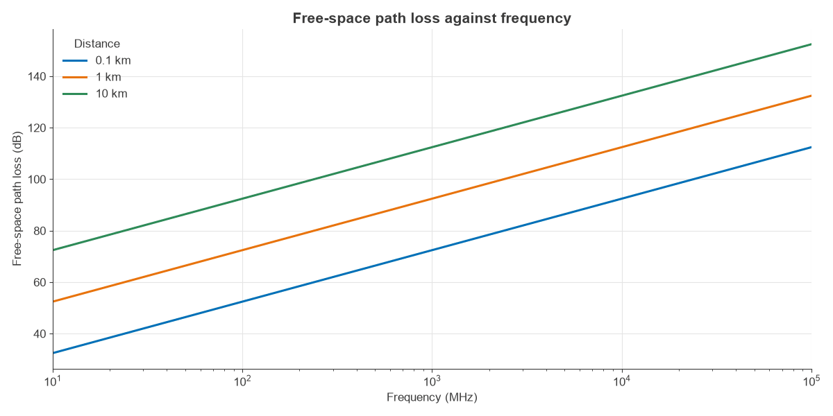
At 1 km this reduces to 32.45 + 20 log fMHz. Each doubling of frequency adds 6 dB, the same as doubling distance. The reason is geometry, not air: the wave does not lose more energy at high frequency, but a fixed-gain antenna has a smaller aperture to collect it. The article on free-space path loss gives the derivation.
Worked Example: The Same Link at Three Frequencies
Take a 1 km line-of-sight link with +20 dBm transmit power, dipoles at both ends (2.15 dBi each), 20 MHz noise bandwidth and a 6 dB noise figure.
- Noise floor: −174 + 10 log(20 × 106) + 6 = −95.0 dBm.
- 433 MHz: received power 20 + 4.3 − 85.2 = −60.9 dBm, SNR 34.1 dB.
- 2.4 GHz: received power 20 + 4.3 − 100.1 = −75.8 dBm, SNR 19.2 dB.
- 28 GHz: received power 20 + 4.3 − 121.4 = −97.1 dBm, SNR −2.1 dB.
With identical antenna gains, 28 GHz is 21.3 dB worse than 2.4 GHz, and the link no longer closes. Practical systems at that frequency do not use dipoles.
Antenna Size and the Aperture Argument
A dish or array of fixed physical area has gain G = 4πAe/λ², which grows 6 dB per octave. If both ends use a fixed aperture, this outweighs path loss and net loss falls as frequency rises. Using a 0.1 m² dish with 60% efficiency at each end gives:
| Frequency | Dish gain | Net path loss at 1 km |
|---|---|---|
| 2.4 GHz | 16.8 dBi | 66.4 dB |
| 5.8 GHz | 24.5 dBi | 58.7 dB |
| 28 GHz | 38.2 dBi | 45.0 dB |
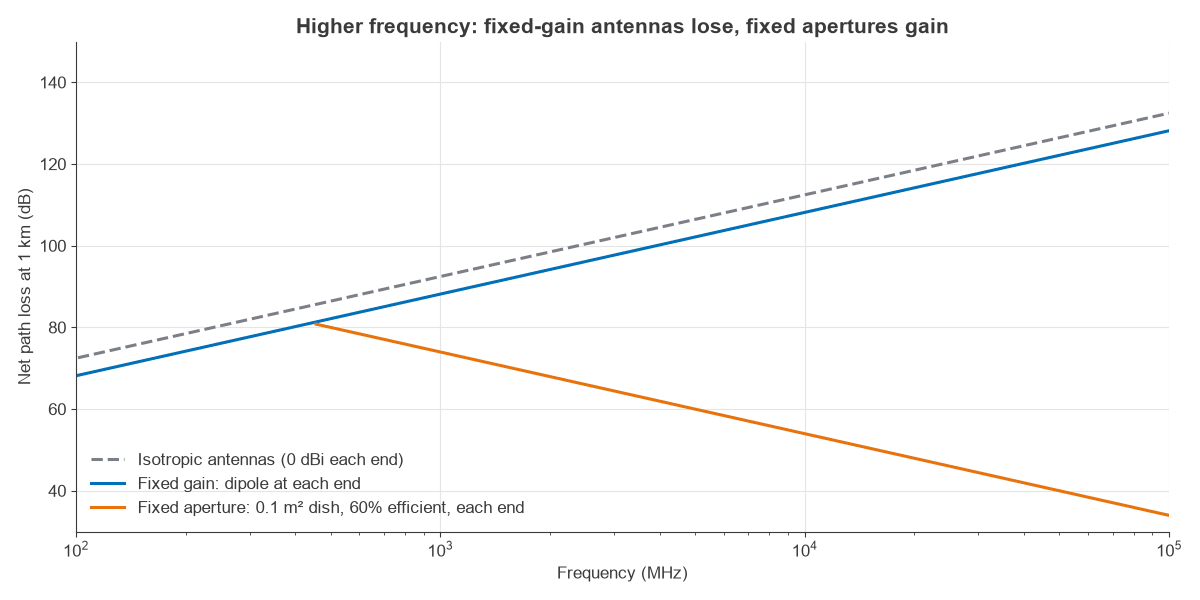
This is the real reason for point-to-point microwave and millimetre-wave beamforming. The cost is a narrow beam that has to be aimed, which leads to the phased arrays used in mmWave radio. The antenna parameters article covers aperture and gain.
Bandwidth and Data Rate
A filter, antenna or amplifier generally handles a given fractional bandwidth, so the absolute bandwidth available scales with carrier frequency. A 5% band is 21.7 MHz at 433 MHz and 1.4 GHz at 28 GHz. Regulators also have more spectrum to give at high frequency.
Shannon’s limit C = B log2(1 + SNR) shows why this matters. 20 MHz at 20 dB SNR supports 133 Mbit/s, while 400 MHz at 10 dB supports 1384 Mbit/s. Bandwidth beats SNR in this comparison, which is why high-capacity systems move up in frequency even with poorer SNR.
Propagation Across RF Frequency Bands
Free space is only the starting point. The propagation mechanism changes across the spectrum, as the following approximate summary shows.
- Below 3 MHz: ground wave follows the Earth, so long range is possible at low power, with little bandwidth.
- 3 to 30 MHz (HF): refraction from the ionosphere gives sky wave paths over thousands of kilometres, varying with time of day and solar activity.
- 30 MHz to 3 GHz (VHF and UHF): mainly line of sight with diffraction and reflection, and useful building penetration, so these bands are in high demand for mobile services.
- 3 to 30 GHz: line of sight, and rain attenuation grows through this range.
- Above 30 GHz: blocked by walls, foliage and often the human body. Oxygen absorption near 60 GHz is roughly 15 dB/km, a large value that limits range and helps frequency reuse.
Wall penetration, diffraction around buildings and foliage loss all generally get worse with frequency. The antennas and propagation part of the Radio Architectures series treats these effects in a design context.
Doppler, Phase Noise and Hardware
Other effects also scale with carrier frequency. Doppler shift is fd = v f/c, so a 30 m/s vehicle sees 90 Hz at 900 MHz and 2.8 kHz at 28 GHz. That shortens channel coherence time and forces more frequent tracking.
Oscillator phase noise also worsens with frequency, about 6 dB per octave when a reference is multiplied up, which limits usable modulation order. Transistor gain falls, line and connector loss grows, and tolerances matter more as wavelength shrinks. A trace length that is negligible at 100 MHz becomes a transmission line at 2.4 GHz.
Interference, Regulation and Frequency Reuse
Frequency also decides who else is on the channel. Spectrum is licensed by band, and each allocation limits power, bandwidth and out-of-band emissions, so a design is rarely free to pick any carrier. Licence-free ISM bands avoid fees, but users there must tolerate interference from every other device, and 2.4 GHz is typically crowded.
Short range can be an advantage. The same frequency can be reused a short distance away when path loss and walls contain the signal, which is why small cells at higher frequencies carry far more traffic per square kilometre than one large low-band cell. Noise sets another limit: external man-made and galactic noise dominates at HF and low VHF, so a very low receiver noise figure gains little there. At UHF and above, the noise figure of the receiver itself usually matters most.
Choosing a Frequency for an RF Communication Link
| Need | Favoured direction | Example |
|---|---|---|
| Long range, low data rate | Lower frequency | Sub-GHz sensor links |
| Building penetration | Below about 3 GHz | Cellular coverage layers |
| High capacity | Higher frequency | mmWave and backhaul |
| Small antenna | Higher frequency | Handheld devices |
| Licence-free operation | ISM bands | 433 MHz, 915 MHz, 2.4 GHz, 5.8 GHz (region dependent) |
Frequently asked questions
Why is frequency important in communication?
It sets wavelength and therefore antenna size, path loss, propagation behaviour and the bandwidth available. The carrier frequency largely decides range and capacity before any other design choice is made.
What is RF communication?
RF communication transfers information by modulating radio-frequency electromagnetic waves. Common examples include broadcast radio, cellular, Wi-Fi, Bluetooth, satellite links and radar.
Why do engineers use higher-frequency waves to send information?
Higher frequencies provide more bandwidth, which supports higher data rates, and they allow compact, high-gain antennas. The trade-offs are shorter range with fixed-gain antennas and poorer penetration.
Does higher frequency mean faster data?
Not directly. Data rate depends on bandwidth and SNR. Higher carriers tend to be faster only because more bandwidth is available there.
Related topics
For how signals sit on a carrier see amplitude modulation, amplitude modulation and demodulation, frequency modulation, frequency shift keying, amplitude shift keying, pulse amplitude modulation and continuous wave modulation. Spectrum views are covered in frequency domain analysis. The RF fundamentals and antennas hubs go further.